
Instruction Manual


14 PowerFlex® DC Drive - Frame A AC Current Transducers for Drives with Bus Bars
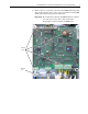
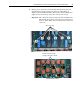
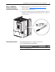
5. While lifting the terminal bus bars out of the drive, slide the AC Current
Transducers off of the bus bars.
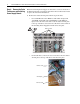
Step 6: Install the New AC
Current Transducers
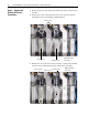
Install the new AC Current Transducers in reverse order of removal as
detailed in Step 5: Remove the Existing AC Current Transducers
above.
• The final tightening torque for the screws connecting the bus bars to the
SCR modules is 2.5…4 N•m (22…35.4 lb•in).
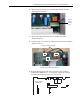
Step 7: Install the Pulse
Transformer and Switching
Power Supply Boards
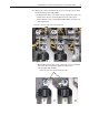
Install the Pulse Transformer and Switching Power Supply boards in reverse
order of removal as detailed in Step 4: Remove the Pulse Transformer and
Switching Power Supply Boards on page 8.
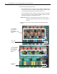
Step 8: Install the Control
EMI Shield and Control
Board
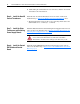
Install the Control EMI Shield and Control board in the reverse order of
removal as detailed in Step 3: Remove the Control EMI Shield and Control
Board on page 6.
ATTENTION: Each gate lead cable must be connected to the
exact connector from which it was removed on the Pulse
Transformer circuit board or damage to the drive may occur.