
Manual

8 PowerFlex® DC Drive Analog and Digital I/O Expansion Circuit Board
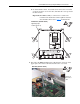
Step 4: Wiring the I/O
Expansion Board
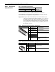
Table 1 Recommended Signal Wire Size
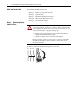
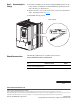
A 75 x 2.5 x 0.4 mm (3.0 x 0.1 x 0.02 in.) flathead screwdriver is
recommended for connecting wire to the terminal block inputs. Strip the
ends of the cables to a length of 6.5 mm (0.26 in.).
Important:To improve the noise immunity it is recommended that you
connect the common of the outputs (terminals 2, 4, 5 and 15 of
the I/O Expansion board) with the ground (terminal 10 or 20)
on the standard I/O terminal blocks on the Control board. If this
is not possible, these terminals must be grounded by means of a
0.1 μf/250V capacitor.
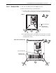
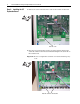
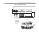
Figure 1 I/O Expansion Board Terminal Block 1 Designations
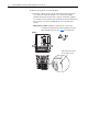
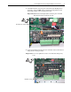
Figure 2 I/O Expansion Board Terminal Block 2 Designations
Wire Type and Size
Tightening Torque
N-m (lb.-in.)Flexible (mm
2
) multi-core (mm
2
)AWG
0.14 - 1.5 0.14 - 1.5 28-16 0.4 (3.5)
No. Signal Description
1 Analog Output 3 (+) ±10V, 5mA maximum
2 Analog Output 3 (–)
3 Analog Output 4 (+) ±10V, 5mA maximum
4 Analog Output 4 (–)
5 Digital Output Common
6 Digital Output 5 (+) Max volt. +30V, max cur. 50mA
7 Digital Output 6 (+)
8 Digital Output 7 (+)
9 Digital Output 8 (+)
10 +24VDC Drive supplied power for Digital
Outputs.
Max volt. +30V, max. cur. 80mA.
No. Signal Description
11 Digital Input 9 Max volt. +30V, max cur. 15V/3.2mA, 24V/
5mA, and 30V/6.4mA.
12 Digital Input 10
13 Digital Input 11
14 Digital Input 12
15 Digital Input Common
2
3
4
5
1
7
8
9
10
6
12
13
14
15
11