
Manual

Publication 20P-IN002A-EN-P - October 2007 P/N 361879-P01
Copyright © 2007 Rockwell Automation. All rights reserved. Printed in USA.
www.rockwellautomation.com
A
mericas:
Rockwell
Automation,
1201
South
Second
Street,
Milwaukee,
WI
53204-2496
USA,
Tel:
(1) 414.382.2000
,
Fax:
(1)
414.382.4444
Europe/Middle East/Africa:
Rockwell
Automation
SA/NV,
Vorstlaan/Boulevard
du Souverain
36,
1170 Brussels,
Belgium,
Tel:
(32) 2 663
0600,
Fax:
(32) 2 663 0640
A
sia
Pacific:
Rockwell
Automation
,
Level 14
,
Core F
,
C
y
ber
p
ort 3
,
100 C
y
ber
p
ort Road
,
Hon
g
Kon
g,
Tel:
(
852
)
2887 4788
,
Fax:
(
852
)
2508 1846
Power, Control and Information Solutions
1S5F19
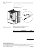
Step 5: Documenting the
Change
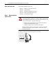
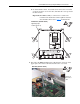
1. Record the installation of the Analog and Digital I/O Expansion circuit
board and date of installation on the Field Installed Option label on the
side of the drive (as shown below).
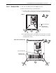
2. Replace the drive covers in the reverse order of removal as described in
Step 2: Opening the Drive on page 3
.
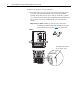
3. Install DPI cable (if present).
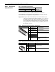
Related Documentation
Allen-Bradley publications are available on the internet at
www.rockwellautomation.com/literature.
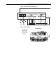
Frame A Shown
For . . . Read this document
Publication
Number
In depth information regarding the
operation of PowerFlex Digital DC drives
User Manual - PowerFlex Digital DC Drives 20P-UM001…