
Instruction Manual


4-6 Troubleshooting
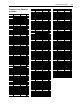
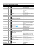
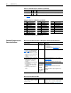
Table 4.B Fault Cross Reference – by Number
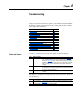
Clearing Alarms
Alarms are automatically cleared when the condition that caused the alarm
is no longer present.
Alarm Descriptions
No.
(1)
(1)
Fault numbers not listed are reserved for future use.
Fault No.
(1)
Fault No.
(1)
Fault
2 Auxiliary Input 41 Phase UV Short 81- 85 Port 1-5 DPI Loss
3 Power Loss 42 Phase VW Short 87 IXo VoltageRange
4 UnderVoltage 43 Phase UW Short 88 Software Fault
5 OverVoltage 48 Params Defaulted 89 Software Fault
7 Motor Overload 49 Drive Powerup 93 Hardware Fault
8 Heatsink OvrTemp 51 Flt QueueCleared 100 Parameter Chksum
9 Trnsistr OvrTemp 52 Faults Cleared 101-103 UserSet Chksum
12 HW OverCurrent 55 Cntl Bd Overtemp 104 Pwr Brd Chksum1
13 Ground Fault 63 Shear Pin 105 Pwr Brd Chksum2
24 Decel Inhibit 64 Drive OverLoad 106 Incompat MCB-PB
25 OverSpeed Limit 68 Gate Kill 107 Replaced MCB-PB
29 Analog In Loss 69 DB Resistance 108 Anlg Cal Chksum
33 Auto Rstrt Tries 71- 75 Port 1-5 Adapter 120 I/O Mismatch
36 SW OverCurrent 77 IR Volts Range 121 I/O Comm Loss
38 Phase U to Grnd 78 FluxAmpsRef Rang 122 I/O Failure
39 Phase V to Grnd 79 Excessive Load 130 Hardware Fault
40 Phase W to Grnd 80 AutoTune Aborted 131 Hardware Fault
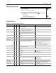
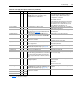
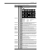
Table 4.C Alarm Descriptions and Actions
Alarm No. Type
(1)
Description
Analog In Loss 5
➀
An analog input is configured for “Alarm” on signal loss and signal
loss has occurred.
Bipolar Conflict 20
➁
Parameter 190 [Direction Mode] is set to “Bipolar” or “Reverse Dis”
and one or more of the following digital input functions is configured:
“Fwd/Reverse,” “Run Forward,” “Run Reverse,” “Jog Forward” or
“Jog Reverse.”
Decel Inhibt 10
➀
Drive is being inhibited from decelerating.
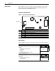
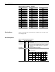
Dig In ConflictA 17
➁
Digital input functions are in conflict. Combinations marked with a
“ ” will cause an alarm.
Acc2/Dec2 Accel 2 Decel 2 Jog
Jog
Fwd
Jog
Rev
Fwd/
Rev
Acc2 / Dec2
Accel 2
Decel 2
Jog*
Jog Fwd
Jog Rev
Fwd/Rev