
Instruction Manual

3-30 Programming and Parameters
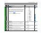
INPUTS & OUTPUTS
Digital Inputs
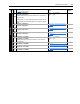
361
362
363
364
365
366
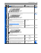
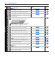
[Digital In1 Sel]
[Digital In2 Sel]
[Digital In3 Sel]
[Digital In4 Sel]
[Digital In5 Sel]
[Digital In6 Sel]
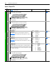
Selects the function for the digital inputs.
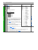
(1)
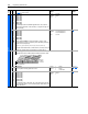
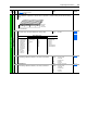
Speed Select Inputs.
To access Preset Speed 1, set [Speed Ref x Sel] to “Preset Speed 1.”
Type 2 Alarms - Some digital input programming may cause conflicts
that will result in a Type 2 alarm. Example: [Digital In1 Sel] set to
option 5 “Start” in 3-wire control and [Digital In2 Sel] set to option 7
“Run” in 2-wire.
Refer to Table 4.C for information on resolving this type of conflict.
(2)
When [Digital Inx Sel] is set to option 2 “Clear Faults,” the Stop button
cannot be used to clear a fault condition.
(3)
Typical 3-Wire Inputs - Requires that only 3-wire functions are chosen.
Including 2-wire selections will cause a Type 2 alarm.
Default:
Default:
Default:
Default:
Default:
Default:
Options:
4
5
18
15
16
17
0
1
2
3
4
5
6
7
8
9
10
11
12
13
14
15-17
18
19
20
21
22
23
24
25
26
27
28
29
30
“Stop – CF”
“Start”
“Auto/ Manual”
“Speed Sel 1”
“Speed Sel 2”
“Speed Sel 3”
“Not Used”
“Enable”
(6) (8)
“Clear Faults” (CF)
(2)
“Aux Fault”
“Stop – CF”
(8)
“Start”
(3) (7)
“Fwd/ Reverse”
(3)
“Run”
(4) (8)
“Run Forward”
(4)
“Run Reverse”
(4)
“Jog”
(3)
“Jog Forward”
(4)
“Jog Reverse”
(4)
“Stop Mode B”
“Bus Reg Md B”
“Speed Sel 1-3”
(1)
“Auto/ Manual”
(5)
“Local”
“Acc2 & Dec2”
“Accel 2”
“Decel 2”
“MOP Inc”
“MOP Dec”
“Excl Link”
“PI Enable”
“PI Hold”
“PI Reset”
“Pwr Loss Lvl”
“Precharge En”
100
156
162
096
140
194
380
124
(4)
Typical 2-Wire Inputs - Requires that only 2-wire functions are chosen. Including 3-wire selections will cause a Type
2 alarm. See Table 4.C for conflicts.
(5)
Auto/Manual - Refer to page 1-29 for details.
(6)
Opening an “Enable” input will cause the motor to coast-to-stop, ignoring any programmed Stop modes.
(7)
A “Dig In ConflictB” alarm will occur if a “Start” input is programmed without a “Stop” input.
(8)
Refer to the Sleep-Wake Mode Attention statement on page 3-17.
File
Group
No.
Parameter Name & Description
See page 3-2 for symbol descriptions
Values Related
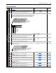
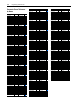
3 2 1 Auto Reference Source
0
0
0
0
1
1
1
1
0
0
1
1
0
0
1
1
0
1
0
1
0
1
0
1
Reference A
Reference B
Preset Speed 2
Preset Speed 3
Preset Speed 4
Preset Speed 5
Preset Speed 6
Preset Speed 7