
Instruction Manual


Programming and Parameters 3-25
Communication File
File
Group
No.
Parameter Name & Description
See page 3-2 for symbol descriptions
Values Related
COMMUNICATION
Comm Control
270 [DPI Data Rate]
Sets the baud rate for attached drive peripherals. When changing this
value the drive must be reset for the change to take affect.
Default:
Options:
1
0
1
“500 kbps”
“125 kbps”
“500 kbps”
271 [Drive Logic Rslt]
The final logic command resulting from the combination of all DPI and discrete
inputs. This parameter has the same structure as the product-specific logic
command received via DPI and is used in peer-to-peer communications.
Read Only
272 [Drive Ref Rslt]
Present frequency reference scaled as a DPI reference for peer-to-peer
communications. The value shown is the value prior to the accel/decel
ramp and the corrections supplied by slip comp, PI, etc.
Default:
Min/Max:
Units:
Read Only
–/+32767
1
273 [Drive Ramp Rslt]
Present frequency reference scaled as a DPI reference for peer-to-peer
communications. The value shown is the value after the accel/decel ramp,
but prior to any corrections supplied by slip comp, PI, etc.
Default:
Min/Max:
Units:
Read Only
–/+32767
1
Masks & Owners
276 [Logic Mask]
Determines which adapters can control the drive. If the bit for an adapter is set to “0,” the adapter will have no control
functions except for stop.
288 thru 297
277 [Start Mask]
Controls which adapters can issue start commands.
See [Logic Mask]. 288 thru 297
278 [Jog Mask]
Controls which adapters can issue jog commands.
See [Logic Mask]. 288 thru 297
279 [Direction Mask]
Controls which adapters can issue forward/reverse direction commands.
See [Logic Mask]. 288 thru 297
280 [Reference Mask]
Controls which adapters can select an alternate reference; [Speed Ref A,
B Sel] or [Preset Speed 1-7].
See [Logic Mask]. 288 thru 297
281 [Accel Mask]
Controls which adapters can select [Accel Time 1, 2].
See [Logic Mask]. 288 thru 297
282 [Decel Mask]
Controls which adapters can select [Decel Time 1, 2].
See [Logic Mask]. 288 thru 297
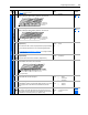
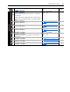
0110000101110000
10 01234567891112131415
1 =Condition True
0 =Condition False
x =Reserved
Bit #
Stop
Start
Jog
Clear Fault
Forward
Reverse
Local Contrl
Mop Inc
Accel 1
Accel 2
Decel 1
Decel 2
Spd Ref ID 0
(1)
Spd Ref ID 1
(1)
Spd Ref ID 2
(1)
MOP Dec
Bits
(1)
Description14 13 12
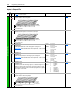
0
0
0
0
1
1
1
1
0
0
1
1
0
0
1
1
0
1
0
1
0
1
0
1
No Command - Man. Mode
Ref A Auto
Ref B Auto
Preset 3 Auto
Preset 4 Auto
Preset 5 Auto
Preset 6 Auto
Preset 7 Auto
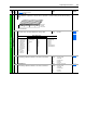
111111xxxxxxxxxx
10 01234567891112131415
1 =Control Permitted
0 =Control Masked
x =Reserved
Bit #
Factory Default Bit Values
Digital In
DPI Port 1
DPI Port 2
DPI Port 3
DPI Port 4
DPI Port 5