
Instruction Manual

3-18 Programming and Parameters
DYNAMANIC CONTROL
Power Loss
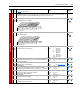
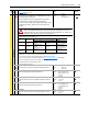
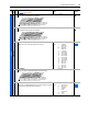
184 [Power Loss Mode]
Sets the reaction to a loss of input power. Power loss is recognized when:
• DC bus voltage is <
73% of [DC Bus Memory] and [Power Loss Mode]
is set to “Coast.”
• DC bus voltage is <
82% of [DC Bus Memory] and [Power Loss Mode]
is set to “Decel.”
Default:
Options:
0
0
1
2
3
4
“Coast”
“Coast”
“Decel”
“Continue”
“Coast Input”
“Decel Input”
013
, 185
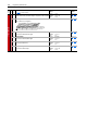
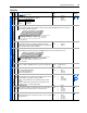
185 [Power Loss Time]
Sets the time that the drive will remain in power loss mode before a fault
is issued.
Default:
Min/Max:
Units:
0.5 Secs
0.0/60.0 Secs
0.1 Secs
184
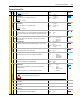
186 [Power Loss Level]
Sets the level at which the [Power Loss Mode] selection will occur.
Default:
Min/Max:
Units:
Drive Rated Volts
0.0/999.9 VDC
0.1 VDC
File
Group
No.
Parameter Name & Description
See page 3-2 for symbol descriptions
Values Related
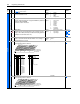
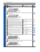
The drive can use the percentages referenced in [Power Loss Mode] or a trigger point can be set for line loss
detection as follows:
V
trigger
= [DC Bus Memory] – [Power Loss Level]
A digital input (programmed to “29, Pwr Loss Lvl”) is used to toggle between fixed percentages and the detection
level.
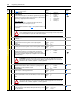
!
ATTENTION: Drive damage can occur if proper input impedance is not provided as explained below.
If the value for [Power Loss Level] is greater than 18% of [DC Bus Memory], the user must provide a
minimum line impedance to limit inrush current when the power line recovers. The input impedance
should be equal to or greater than the equivalent of a 5% transformer with a VA rating 5 times the
drives input VA rating.