
Instruction Manual


3-2 Programming and Parameters
How Parameters are
Organized
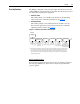
The LCD HIM displays parameters in a File-Group-Parameter or Numbered
List view order. To switch display mode, access the Main Menu, press ALT,
then Sel while cursor is on the parameter selection. In addition to using
[Param Access Lvl]
, the user has the option to display all parameters,
commonly used parameters, or diagnostic parameters.
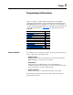
File-Group-Parameter Order
This simplifies programming by grouping parameters that are used for
similar functions. The parameters are organized into 6 files in Basic
Parameter view or 7 files in Advanced Parameter view. Each file is divided
into groups, and each parameter is an element in a group. By default, the
LCD HIM displays parameters by File-Group-Parameter view.
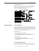
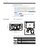
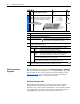
No. Description
➊
File – Lists the major parameter file category.
➋
Group – Lists the parameter group within a file.
➌
No. – Parameter number. = Parameter value cannot be changed until drive is stopped.
= 32 bit parameter in the Standard Control option.
➍
Parameter Name & Description – Parameter name as it appears on an LCD HIM, with a brief
description of the parameters function.
➎
Values – Defines the various operating characteristics of the parameter. Three types exist.
ENUM Default:
Options:
Lists the value assigned at the factory. “Read Only” = no default.
Displays the programming selections available.
Bit Bit: Lists the bit place holder and definition for each bit.
Numeric Default:
Min/Max:
Units:
Lists the value assigned at the factory. “Read Only” = no default.
The range (lowest and highest setting) possible for the parameter.
Unit of measure and resolution as shown on the LCD HIM.
Important: Some parameters will have two unit values. Analog inputs can be set for
current or voltage with [Anlg In Config], parameter 320.
Important: When sending values through DPI ports, simply remove the decimal
point to arrive at the correct value (i.e. to send “5.00 Hz,” use “500”).
➏
Related – Lists parameters (if any) that interact with the selected parameter. The symbol “ ”
indicates that additional parameter information is available in Appendix
D.
File
Group
No.
Parameter Name & Description Values
Related
UTILITY
Drive . . .
198 Load Frm Usr Set]
Loads a previously saved set of parameter
values from a selected user set location in
drive nonvolatile memory to active drive
memory.
Default:
Options:
0
0
1
2
3
“Ready”
“Ready”
“User Set 1”
“User Set 2”
“User Set 3”
199
Diagnostics
216 [Dig In Status]
Status of the digital
inputs.
000000xxxxxxxxxx
10 01234567891112131415
1 = Input Present
0 = Input Not Present
x =Reserved
Bit #
Digital In1
Digital In2
Digital In3
Digital In4
Digital In5
Digital In6
➊➌➋➏➎➍
32