
Instruction Manual


2-2 Start Up
Applying Power to the Drive
❏ 4. Apply AC power and control voltages to the drive.
If any of the six digital inputs are configured to “Stop – CF” (CF = Clear
Fault) or “Enable,” verify that signals are present or reconfigure [Digital
Inx Sel]. If an I/O option is not installed (i.e. no I/O terminal block),
verify that [Digital Inx Sel] is not configured to “Stop – CF” or “Enable.”
If this is not done, the drive will not start. Refer to Alarm Descriptions
on
page 4-6 for a list of potential digital input conflicts. If a fault code
appears, refer to Chapter
4.
If the STATUS LED is not flashing green at this point, refer to LED
Status Definitions in Table 2.A
.
❏ 5. Proceed to Start-Up Routines.
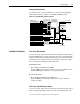
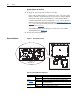
Status Indicators
Figure 2.1 Drive Status Indicator
Table 2.A Ready LED Status Indications
Control Panel
Inverter
Status LED
Color State Description
Green Flashing Drive ready, but not running and no faults are present.
Steady Drive running, no faults are present.
Ye l l o w
See page 4-2
.
Flashing The drive is not ready. Check parameter 214 [Start Inhibits].
Steady An alarm condition exists. Check parameters 211 [Drive Alarm 1]
and 212 [Drive Alarm 2].
Red
See page 4-3
.
Flashing A fault has occurred.
Steady A non-resettable fault has occurred.