
Instruction Manual

Installation/Wiring 1-3
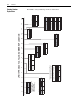
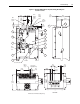
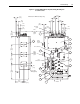
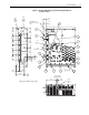
Figure 1.1 B-Frame LPM15 Drive Component, Wiring, Mounting and
Coolant Locations
6
7
5
14
13
11
2
3
1
8
4
12
10
9
165.0
[6.50]
275.5
[10.85]
50.4
[1.98]
User Connections
Drive
Input
Wiring
(6) Pl.
Drive
Output
Wiring
(3) Pl.
DPI
Comm.
Port
6.4
[0.25]
(6) Pl.
6.4
[0.25]
(3) Pl.
Ø7.1
[Ø0.28]
(6) Pl.
User Control
Wiring Openings
Dimensions in millimeters and [inches]
Ø9.5
[Ø0.37]
(3) Pl.
128.3
[5.05]
52.3
[2.06]
(2) Pl.
17.4
[0.69]
(6) Pl.
19.1
[0.75]
(6) Pl.
38.1
[1.50]
(3) Pl.
22.2
[0.88]
(3) Pl.
TOP VIEW
300.8
[11.84]
39.7
[1.56]
Ø19.1
[Ø0.75]
Typ.
326.6
[12.8
UV
W
L1 L4 L2 L5 L3 L6
76.2
[3.00]
76.2
[3.00]
Air Flow
123.1
[4.85]