
Instruction Manual
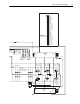


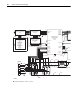
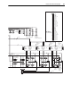


G-2 D-Frame LPM15 Drive Wiring Diagram
L3N
L6
GND
L4
L5
L2
L3
L1
L1N L2N
L2PL1P
SCR5
L6N L5N
L3P
L6P L5P
SCR6
L4N
179393
179395
L4P
SCR4
179397
179392
3
4
179398
INVERTER CONTROL
See DETAIL A for
User Connections
STANDARD I/O OPTION(S)
180505-A01
SCR1
SCR2
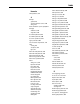
DeviceNet
RIO
BOARD OPTION(S)
J1
J2
J5
TB1
J7
J2
J2
J3
COMMUNICATIONS INTERFACE
J1
179726
POWER INTERFACE
J2
J5
Part of 180528-Q02
SCR3
179394 179396
J11
J9
J10
J1
180493-A04
CONTROL ASSEMBLY
179852
179447
1
2
J1
J7
J6
Part of 179853
179694-Q02 179695-Q02
194706-Q02
ControlNet-Coax
ControlNet-Fiber
RS485, DF-1
RS485, HVAC
PROFIBUS DPV1
Interbus
LonWorks
EtherNet/IP
N/A
24V DC - 180524-A01
120V AC - 180525-A01
NO I/O
OPTIONAL
OPTIONAL
COMMUNICATION
1000HP
J4
J3
Jumper
180497-Q01
Main Control
Interface
AC Line Sync
Gate Kill
SCR Gate-
Cathode
S1, S2, S3
SCR Gate-
Cathode
S4, S5, S6
Gate Driver
Interface
Current
Feedback
25 KHz PS
DC Bus/
Cap Bank
Mid-Point
Bleeder/
Temp Sw/
Fan Power
179209
Reactor
30 uh
(6-Pulse Configuration)
179353
6 Places
NOTES:
1.) Symbol designates PIN 1 location of connectors.
179391
AC Power
Input Leads