
Instruction Manual


P-2 Overview
Manual Conventions
• In this manual we refer to the LPM15 Adjustable Frequency AC Drive
as; drive, LPM15 or LPM15 Drive.
• To help differentiate parameter names and LCD display text from other
text, the following conventions will be used:
– Parameter Names will appear in [brackets].
For example: [DC Bus Voltage].
– Display Text will appear in “quotes.” For example: “Enabled.”
• The following words are used throughout the manual to describe an
action:
General Precautions
Word Meaning
Can Possible, able to do something
Cannot Not possible, not able to do something
May Permitted, allowed
Must Unavoidable, you must do this
Shall Required and necessary
Should Recommended
Should Not Not recommended
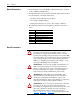
!
ATTENTION: This drive contains ESD (Electrostatic
Discharge) sensitive parts and assemblies. Static control
precautions are required when installing, testing, servicing or
repairing this assembly. Component damage may result if ESD
control procedures are not followed. If you are not familiar with
static control procedures, refer to Allen-Bradley publication
8000-4.5.2, “Guarding Against Electrostatic Damage” or any
other applicable ESD protection handbook.
!
ATTENTION: An incorrectly applied or installed drive can
result in component damage or a reduction in product life.
Wiring or application errors, such as, undersizing the motor,
incorrect or inadequate AC supply, or excessive ambient
temperatures may result in malfunction of the system.
!
ATTENTION: Only qualified personnel familiar with
adjustable frequency AC drives and associated machinery
should plan or implement the installation, start-up, and
subsequent maintenance of the system. Failure to comply may
result in personal injury and/or equipment damage.
!
ATTENTION: To avoid an electric shock hazard, verify that
the voltage on the bus capacitors has discharged before
performing any work on the drive. After removing power to the
drive, wait 5 minutes for the bus capacitors to discharge.
Measure the DC bus voltage at the locations shown in
Figure 4.2
, Figure 4.3 or Figure 4.4. The voltage must be zero.