
Owner's manual


Cooling Loop Installation 4-9
PowerFlex 700L Frames 2, 3A, and 3B Liquid-Cooled AC Drives User Manual
Publication 20L-UM001E-EN-P
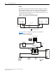
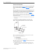
2. Using a backup wrench on the Complete Drive fitting, tighten the
swivel nut fitting by either of the following two methods:
– Hex flats from wrench resistance method (recommended): one (1)
hex flat from wrench resistance.
– Torque method: 103…109 N•m (76…81 lb•ft).
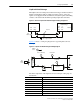
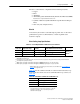
Figure 4.9 Frame 3A and 3B Complete Drive Mating Coolant Connection
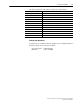
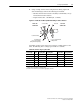
Depending on the location of the heat exchanger or chiller relative to the
drive, the following drive cooling loop hose kits are available.
Table 4.A Drive Cooling Loop Hose Kits
DRIVE SIDE
CONNECTION
37° Flare Fitting
Backup Wrench
(use to pre
vent twisting
dur
ing swivel nut tightening)
Do not use Backup Wrench
on fitting locknut
1 5/8" Wrench Flats
Swivel Nut
USER SIDE
CONNECTION
Hose Length
Hoses
in Kit
Drive Side
(1)
Coupling Size
Heat Exchanger Side
Coupling Size
Used With
Hose Kit
(2)
Catalog Number
3 m (10 ft) 2 0.75 inch 0.75 inch Frame 2 20L-GH10-B1
9.1 m (30 ft) 2 0.75 inch 0.75 inch Frame 2 20L-GH30-B1
3 m (10 ft) 2 1 inch 1 inch with 90° elbow Frame 3A 20L-GH10-A2
9.1 m (30 ft) 2 1 inch 1 inch with 90° elbow Frame 3A 20L-GH30-A2
3 m (10 ft) 2 1 inch 1 inch Frame 3B 20L-GH10-A1
9.1 m (30 ft) 2 1 inch 1 inch Frame 3B 20L-GH30-A1
(1)
All drive side hose kit fittings are 37 degree flare.
(2)
Each hose kit contains two (2) hoses and the appropriate connectors.