
Owner's manual


3-38 Frame 3A and 3B Installation
PowerFlex 700L Frames 2, 3A, and 3B Liquid-Cooled AC Drives User Manual
Publication 20L-UM001E-EN-P
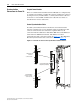
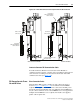
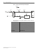
Figure 3.35 Frame 3A DPI Connection Points
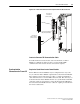
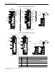
Figure 3.36 Frame 3B DPI Connection Points
Power Module
HIM Option
Top
Inverter
Bottom
Inverter
➎
➋
Internal
DPI Cable
Internal
DPI Cable
Top Inverter
DPI Port
No Connection
Permitted
Active
Converter
PCB
Bottom of Power Module
Combined
Active Converter/Inverter
Power Module
Dual Inverter Power Module
External
HIM Option
External
DPI Cable
➊
Communications
Adapter Option
➍
Power Module
HIM Option
➊
Communications
Adapter Option
➍
Power Module
HIM Option
➊
Communications
Adapter Option
➍
Top Main
Control PCB
Option
Bottom Main
Control PCB
Option
➋
Bottom Inverter
DPI Port
➋
➌
➋
Active
Converter
PCB
No Connections
Permitted
Blank HIM
No Connection
Permitted
No Communications
Adapter Permitted
Inverter-to-Converter
DPI Cable
Internal
DPI Cable
Internal
DPI Cable
➎
➋
Active Converter Power Module Inverter Power Module
Bottom of Modules
External
HIM Option
Inverter-to-Converter
DPI Cable
External
DPI Cable
Power Module
HIM Option
➊
➍
Communications
Adapter Option
➌
➋
Item Connector Description
➊
DPI Port 1 HIM connection when installed in Power Module.
➋
DPI Port 2 Cable connection for handheld and remote options.
➌
DPI Port 3 or 2 Splitter cable connected to DPI Port 2 provides an additional port.
➍
DPI Port 5 Cable connection for communications adapter.
➎
DPI Port 6 Internal DPI connection to Active Converter PCB.