
Owner's manual


3-24 Frame 3A and 3B Installation
PowerFlex 700L Frames 2, 3A, and 3B Liquid-Cooled AC Drives User Manual
Publication 20L-UM001E-EN-P
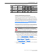
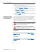
Depending on the supplied AC line voltage used to power the drive, connect
FU1 and FU2 to TB1 in accordance with Table 3.A
. See Figure 3.29 or
Figure 3.30
for fuse and terminal block locations.
Table 3.A Input Voltage Setting for Control Transformer
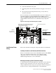
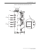
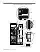
Figure 3.23 Frame 3A Regenerative Drive Input Power and PE Wiring
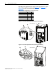
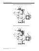
Figure 3.24 Frame 3B Regenerative Drive Input Power and PE Wiring
Supplied Input Voltage From To
For all input voltages FU1 TB1-1
380/415V AC FU2 TB1-2
440/480V AC FU2 TB1-3
575/600V AC FU2 TB1-4
690V AC FU2 TB1-5
L1
L2
L3
PE
INPUT FILTER BAY
DETAIL
➊
➋
L1
PE
L2
L3
INPUT FILTER BAY
DETAIL
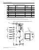
L1
PE
L2
L3
L1
PE
L2
L3
➊
➋