
Owner's manual

Frame 3A and 3B Installation 3-7
PowerFlex 700L Frames 2, 3A, and 3B Liquid-Cooled AC Drives User Manual
Publication 20L-UM001E-EN-P
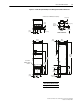
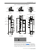
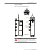
Figure 3.6 Frame 3B Power Module Installation Dimensions
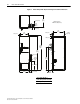
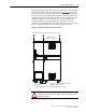
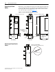
Recommended Mounting Clearances for Power Modules
Specified vertical clearance requirements (Figure 3.7) are intended to be
from power module to cabinet surface. Other objects can occupy this space;
however, reduced air flow can cause protection circuits to fault the module.
In addition, inlet air temperature must not exceed the product specification.
44 (1.75)
44 (1.75)
23 (0.90)
21 (0.81)
21 (0.81)
76 (3.00)
44 (1.75)
44 (1.75)
16 (0.62)
16 (0.62)
25 (1.00)
37 (1.44)
29 (1.12)
57 (2.25)
DETAIL A
BACK VIEW LEFT SIDE VIEW FRONT VIEW
DETAIL B DETAIL C
51 (2.00)
97 (3.82)
55 (2.16)
57 (2.24)
57 (2.24)
51 (1.99)
37 (1.46)
104 (4.08)
89 (3.51)
75 (2.95)
24 (0.94)
567 (22.32)
51 (1.99)
AIRFLOW
1326 (52.20)
275 (10.83)
255 (10.05)
461 (18.16)
231 (9.09)
231 (9.09)
265 (10.44)
402 (15.81)
368 (14.50)
1200 (47.25)
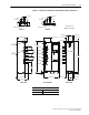
12 (0.45)
39 (1.56)
175 (6.89)
15 (0.60)
39 (1.56)
175 (6.89)
See
DETAIL B
See
DETAIL A
DC Neg.
DC Pos.
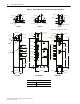
Ø
14 (
Ø
0.56)
Ø
14 (
Ø
0.56)
Ø
14 (
Ø
0.56)
See DETAIL C
GRD
R/L1
or
U/T1
S/L2
or
V/T2
T/L3
or
W/T3
Dimensions are in millimeters and (inches).
Approximate Weight
Power Module Power Module and Packaging
132 kg (290 lb) 166 kg (365 lb)