
Owner's manual

PowerFlex 700L Frames 2, 3A, and 3B Liquid-Cooled AC Drives User Manual
Publication 20L-UM001E-EN-P
Chapter 3
Frame 3A and 3B Installation
Because most start-up difficulties are the result of incorrect wiring, take
every precaution to verify that the wiring is completed as instructed. Read
and understand all items before beginning actual installation.
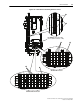
Drive Components
Frame 3A and 3B complete drives are comprised of an Input Filter Bay and a
Power Module Bay. For Frame 3A drives, the Power Module Bay contains a
combined Converter/Inverter Power Module. For Frame 3B drives, the
Power Module Bay contains separate Converter and Inverter Power Modules.
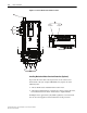
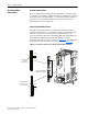
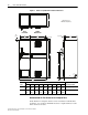
Total Area Required for Drive Installation
Overall drive dimensions are shown in Figure 3.1 as an aid in calculating
the total area required for installing Frame 3A and 3B drives.
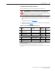
Topic Page
Drive Components
3-1
Equipment Lifting 3-8
Supporting the Power Module 3-12
Removing the Power Module Covers 3-12
Removing the Active Converter Power Module Control Cassette 3-13
Removing the Inverter Power Module Control Cassette 3-14
Verifying the Drive’s Watts Loss Rating 3-16
Determining Wire Routing for Control, Ground, Drive Input, and Motor Output 3-16
Grounding the Power Module 3-22
Ungrounded or Resistive Grounded Installations 3-22
Installing Input Power Wiring 3-23
Installing Output Power Wiring 3-29
Installing Control Wiring from the Input Filter Bay to the Power Module Bay 3-30
Synchronization Connections for Frame 3A 3-34
Synchronization Connections for Frame 3B 3-35
DPI Connections for Frame 3A and 3B Drives 3-37
Coolant Loop Connections 3-39
!
ATTENTION: The following information is merely a guide for
proper installation. Rockwell Automation does not assume
responsibility or liability for the compliance or noncompliance to
any code, national, local or otherwise for the proper installation
of this drive or associated equipment. A hazard of personal injury
and/or equipment damage exists if codes are ignored during
installation.