
Owner's manual

Frame 2 Installation 2-15
PowerFlex 700L Frames 2, 3A, and 3B Liquid-Cooled AC Drives User Manual
Publication 20L-UM001E-EN-P
Installing Input Power Wiring to the Drive
Use the following steps to connect AC input power to the drive.
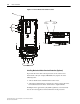
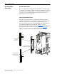
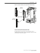
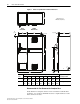
1. Connect the three-phase AC input power leads (three-wire 380-480V
AC) to the R/L1, S/L2, and T/L3 input power terminals on the Frame 2
drive.
For terminal locations, see Figure 2.15
.
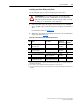
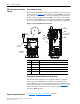
2. Tighten the AC input power terminal connections to the recommended
torque as shown in Table 2.B
.
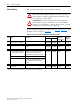
Table 2.B Frame 2 Drive Power Terminal Specifications
!
ATTENTION: Do not route signal and control wiring with
power wiring in the same conduit. This can cause interference
with drive operation. Failure to observe this precaution can result
in damage to, or destruction of, the equipment.
Item Name Description
Recommended
Tightening
Torque (+
10%)
Terminal
Bolt Size
(1)
(1)
Apply counter torque to the nut on the other side of terminations when tightening or loosening the terminal bolt to
avoid damage to the terminal.
➊
Input Power Bus Bar
(2)
R/L1, S/L2, T/L3
(2)
These connections are bus bar type terminations and require the use of lug connectors.
Input power 40 N•m
(354 lb•in)
M8
➋
Output Power Bus Bar
(2)
U/T1, V/T2, W/T3
Motor connections 40 N•m
(354 lb•in)
M8
➌
PE, Motor Ground Bus Bar
(2)
Terminating point for wiring
shields and grounds
40 N•m
(354 lb•in)
M8
➍
DC Bus Test Point Socket
(3)
(2 Terminals; DC+, DC-)
(3)
Use only to verify that DC bus capacitors are discharged before servicing the Power Module. No other external use
is permitted.
4 mm socket for DC bus
voltage measurement only
——