User Manual PowerFlex 700L Liquid-Cooled Adjustable Frequency AC Drive Frames 2, 3A, and 3B
Important User Information Solid-state equipment has operational characteristics differing from those of electromechanical equipment. Safety Guidelines for the Application, Installation and Maintenance of Solid State Controls (publication SGI-1.1 available from your local Rockwell Automation sales office or online at http://www.rockwellautomation.com/literature/) describes some important differences between solid-state equipment and hard-wired electromechanical devices.
Summary of Changes The information below summarizes the changes made to this manual since its last release (August 2008). Description of Changes Page Revised and re-organized information in Chapter 4. 4-1…4-11 Revised information for Electronic Motor Overload Protection in the “Control” section of the specification. A-3 Revised information in the section “Fuse and Circuit Breaker Ratings.
soc-ii Summary of Changes Notes: PowerFlex 700L Frames 2, 3A, and 3B Liquid-Cooled AC Drives User Manual Publication 20L-UM001E-EN-P
Table of Contents Important User Information . . . . . . . . . . . . . . . . . . . . . . . . . . . . . . . . . . . . . . . . . . . . . . . 1-2 Preface Overview Who Should Use this Manual? . . . . . . . . . . . . . . . . . . . . . . . . . . . . . . . . . . . . . . . . . . . . . What Is Not in this Manual . . . . . . . . . . . . . . . . . . . . . . . . . . . . . . . . . . . . . . . . . . . . . . . . PowerFlex 700L Active Converter Power Module Information . . . . . . . . . . . . . . . . . .
ii Table of Contents Equipment Lifting . . . . . . . . . . . . . . . . . . . . . . . . . . . . . . . . . . . . . . . . . . . . . . . . . . . . . . . 2-3 Attaching the Lifting Feet to the Drive . . . . . . . . . . . . . . . . . . . . . . . . . . . . . . . . . . . . . 2-4 Attaching the Lifting Hardware to the Drive . . . . . . . . . . . . . . . . . . . . . . . . . . . . . . . . . 2-4 Connecting Lifting Hooks to Proper Locations. . . . . . . . . . . . . . . . . . . . . . . . . . . . . . .
Table of Contents Removing the Inverter Power Module Control Cassette. . . . . . . . . . . . . . . . . . . . . . . . . PowerFlex 700 Vector Control Cassette (standard) . . . . . . . . . . . . . . . . . . . . . . . . . . PowerFlex 700S Phase II Control Cassette (optional) . . . . . . . . . . . . . . . . . . . . . . . . Verifying the Drive’s Watts Loss Rating . . . . . . . . . . . . . . . . . . . . . . . . . . . . . . . . . . . . . Installing the Vented Top Cover . . . . . . . . . . . . . . . . . . . . . . .
iv Table of Contents Chapter 5 Programming and Parameters Affected 700 Vector Control Parameters . . . . . . . . . . . . . . . . . . . . . . . . . . . . . . . . . . . . . . Utility File . . . . . . . . . . . . . . . . . . . . . . . . . . . . . . . . . . . . . . . . . . . . . . . . . . . . . . . . . . . Communication File . . . . . . . . . . . . . . . . . . . . . . . . . . . . . . . . . . . . . . . . . . . . . . . . . . . Affected 700S Phase II Control Parameters . . . . . . . . . . . . . . . . . . . . .
Preface Overview This manual provides the basic information needed to install, start-up, and troubleshoot the PowerFlex 700L Liquid-Cooled AC Drive. Topic Page Who Should Use this Manual? P-1 What Is Not in this Manual P-1 Additional Resources P-2 Manual Conventions P-3 General Precautions P-4 Catalog Number Explanation P-5 Complete Drive Data Nameplate Locations P-7 Who Should Use this Manual? This manual is intended for qualified personnel.
P-2 Overview HIM (Human Interface Module) Information For an overview of the HIM operation, see the PowerFlex 700 Adjustable Frequency AC Drive User Manual - Series B, publication 20B-UM002, or the PowerFlex 700S High Performance AC Drive - Phase II Control User Manual, publication 20D-UM006.
Overview Title P-3 Publication Hi-Resolution (Stegmann) Feedback Option Card Installation Instructions for PowerFlex 700S Drives 20D-IN001 Resolver Feedback Option Card Installation Instructions for PowerFlex 700S Drives 20D-IN002 Multi-Device Interface Option Card Installation Instructions for PowerFlex 700S Drives 20D-IN004 Second Encoder Option Card for PowerFlex 700S Drives with Phase II Control 20D-IN009 DriveGuard Safe Torque Off Option for PowerFlex 700S Phase II and PowerFlex 700L Drives
P-4 Overview General Precautions ! ! ! ! ! ATTENTION: This drive contains electrostatic discharge (ESD) sensitive parts and assemblies. Static control precautions are required when installing, testing, servicing, or repairing this assembly. Component damage may result if ESD control procedures are not followed. If you are not familiar with static control procedures, see Guarding Against Electrostatic Damage, publication 8000-4.5.2, or any other applicable ESD protection handbook.
Overview P-5 Catalog Number Explanation 1-3 4 5-7 8 9 10 Position 11 12 13 14 15 16 17 18 20L E 800 A 0 E N N A N 1 0 W A a b c d e f g h i j k l m n a d Drive Enclosure Code Type 20L Code PowerFlex 700L b Voltage Rating Code Voltage Ph. C D E F 400V AC 480V AC 600V AC 690V AC 3 3 3 3 Conformal Coating Type A NEMA/UL Type 1, IP20 ✝ No N Open-Chassis Style/IP00 ❖ No ✝ Frame 3 complete drive.
P-6 Overview 1-3 4 5-7 8 9 10 Position 11 12 13 14 15 16 17 18 20L E 800 A 0 E N N A N 1 0 W A a b c d e f g h i j k l m n Code Control k l m Control Option Feedback Additional 700S Configuration Cassette Logic Synch Expansion Link 700VC Base N/A N/A 24V I/O 700VC 2 Base N/A N/A 115V I/O A 700S Ph. II Expanded No No B 700S Ph. II Expanded No Yes C 700S Ph. II Expanded Yes No ▲ D 700S Ph.
Overview Complete Drive Data Nameplate Locations P-7 Frame 2 Drives Figure P.1 shows multiple data nameplate locations for Frame 2 drives. The data and agency markings are different for equipment type. For example, the complete drive is UL listed component; and the Power Modules are UL recognized. Figure P.1 Frame 2 Drive Data Nameplate Locations Cat No. 20LC360N3ENNAN10WA Series: A NEMA Type Complete Regenerative Drive Original Firmware V. x.
P-8 Overview Frames 3A and 3B Drives Figure P.2 shows multiple data nameplate locations for complete Frame 3A/ 3B drives. The data and agency markings are different for equipment type. For example, except for 690V AC input, the complete drive is UL listed component; and the Input Filter and Power Modules are UL recognized. Base Power Module catalog numbers do not reflect the position 14 and position 16 options actually installed inside the Inverter Power Module.
Chapter 1 General Installation Information This chapter provides general information on mounting and wiring PowerFlex 700L Liquid-Cooled AC Drives. Enclosure Ratings Topic Page Enclosure Ratings 1-1 AC Supply Source Considerations 1-1 Power Wiring 1-4 CE Conformity 1-7 C-Tick Conformity 1-9 Using Input/Output Contactors 1-9 PowerFlex 700L Liquid-Cooled AC drives have the following enclosure ratings: • Open-Chassis Style (IP00) - Frame 2: Intended to be installed in an enclosure.
1-2 General Installation Information The kVA of all PowerFlex 700L drives on the distribution system and the system impedance of upstream transformers should be taken into account. ! ATTENTION: To guard against personal injury and/or equipment damage caused by improper circuit breaker selection, use only the recommended circuit breakers specified in Table 1.A.
General Installation Information 1-3 For installations within a cabinet, a single safety ground point or ground bus bar connected directly to building steel should be used. All circuits including the AC input ground conductor should be grounded independently and directly to this ground point or ground bus bar. Figure 1.
1-4 General Installation Information the Active Converter Power Module control cassette PCB assembly terminal block P1. This action also generates a fault in the Inverter Power Module to enunciate this condition. Input Line Branch Circuit Protection ATTENTION: Most codes require that upstream branch circuit protection be provided to protect input power wiring. ! The PowerFlex 700L Frame 2 drive does not provide input power short circuit protection.
General Installation Information 1-5 A variety of cable types are acceptable for drive installations. For many installations, unshielded cable is adequate, provided it can be separated from sensitive circuits. As an approximate guide, allow a spacing of 0.3 meters (1 foot) for every 10 meters (32.8 feet) of length. In all cases, long parallel runs must be avoided. Do not use cable with an insulation thickness less than or equal to 15 mils (0.4mm/0.015 in.). Use Copper wire only.
1-6 General Installation Information and reduce the overall drive performance. These cables are not recommended. Armored Cable Cable with continuous aluminum armor is often recommended in drive system applications or specific industries. It offers most of the advantages of standard shielded cable and also combines considerable mechanical strength and resistance to moisture. It can be installed in concealed and exposed manners and removes the requirement for conduit (EMT) in the installation.
General Installation Information 1-7 Cable Trays and Conduit If cable trays or large conduits are to be used, see the guidelines in Wiring and Grounding Guidelines for Pulse Width Modulated (PWM) AC Drives, publication DRIVES-IN001. ! CE Conformity ATTENTION: To avoid a possible shock hazard caused by induced voltages, unused wires in the conduit must be grounded at both ends.
1-8 General Installation Information • Use of line filters in ungrounded systems is not recommended. • Conformity of the drive with CE EMC requirements does not guarantee an entire machine or installation complies with CE EMC requirements. Many factors can influence total machine/installation compliance. • Non-regenerative PowerFlex 700L Liquid-Cooled AC drives generate conducted low frequency disturbances (harmonic emissions) on the AC supply system which may require mitigation in some applications.
General Installation Information C-Tick Conformity 1-9 Compliance of PowerFlex 700L Liquid-Cooled AC drives with the Australian Radiocommunications Act of 1992 has been demonstrated through compliance with EN61800-3. Both the General Notes and the Essential Requirements for CE Compliance provided above apply to C-Tick compliance for PowerFlex 700L Liquid-Cooled AC drives. C-Tick Declarations of Compliance are available online at www.ab.com/ certification/c-tick/index.html.
1-10 General Installation Information Notes: PowerFlex 700L Frames 2, 3A, and 3B Liquid-Cooled AC Drives User Manual Publication 20L-UM001E-EN-P
Chapter 2 Frame 2 Installation Topic Page Mounting Considerations 2-1 Equipment Lifting 2-3 Mounting Requirements 2-6 Verifying the Drive’s Watts Loss Rating 2-7 Removing the Drive Cover 2-7 Removing the Active Converter Control Cassette 2-7 Removing the Inverter Control Cassette 2-8 Determining Wire Routing for Control, Ground, Drive Input, and Motor Output 2-9 Grounding the Drive 2-11 Ungrounded or Resistive Grounded Installations 2-11 Power Wiring 2-12 Control Wiring 2-18 Syn
2-2 Frame 2 Installation Figure 2.1 Frame 2 Drive Installation Dimensions Ground Terminal with 2 Clearance Holes for M8 Stud Dimensions are in millimeters and (inches). 389.6 (15.34) 351.0 (13.82) 66.6 (2.62) 566.1 (22.29) See DETAIL A 153.8 (6.06) 423.8 (16.68) Motor W/T3 Output V/T2 Terminals U/T1 591.2 (23.28) 3x Clearance Hole for M8 Stud 730.2 (28.75) 955.7 (37.63) 46.9 (1.
Frame 2 Installation 2-3 Figure 2.2 Frame 2 Drive Minimum Mounting Clearances 101.6 mm (4.0 in.) 101.6 mm (4.0 in.) 101.6 mm (4.0 in.) 101.6 mm (4.0 in.) 101.6 mm (4.0 in.) Verifying Drive Input Ratings Match Supplied Power It is important to verify that plant power meets the input power requirements of the PowerFlex 700L Frame 2 drive circuitry. See Appendix A for input power rating specifications. Be sure input power to the drive corresponds to the drive nameplate voltage and frequency.
2-4 Frame 2 Installation Attaching the Lifting Feet to the Drive 1. Remove the four shipping bolts that hold the drive to the skid. 2. Attach the two lifting feet provided with the drive to the bottom drive mounting holes as shown in Figure 2.3. Figure 2.3 Attaching Lifting Feet to the Drive Attaching the Lifting Hardware to the Drive Apply lifting hooks (see Figure 2.4). Take precautions to verify that there are lifting hooks secured in all four locations (Figure 2.5) on the drive. Figure 2.
Frame 2 Installation 2-5 Connecting Lifting Hooks to Proper Locations Locate all four lifting features on the drive (see Figure 2.5). All four locations must be used to maintain the drive center of gravity when lifting. Figure 2.5 Lifting Locations on the Frame 2 Drive Applying Strap Angles TIP: To ensure that this angle is greater than 60°, make the length of chain or cable between the center and the corners (B) longer than the distance between the opposite corners (A). B>A Min.
2-6 Frame 2 Installation Rotating the Drive About the Board Figure 2.6 shows the drive, with the lifting feet attached, on a skid. To avoid damage to the drive input terminals when lifting the drive to a vertical position, do the following. 1. After the straps are in place (see Applying Strap Angles on page 2-5), carefully lift the drive to rotate it 90° to a vertical position. 2. Remove the lifting feet before installing the drive into the enclosure. Figure 2.
Frame 2 Installation Verifying the Drive’s Watts Loss Rating 2-7 When mounting the drive inside of an enclosure, determine the watts loss rating of the drive from Table A.E on page A-6. This table lists the typical full load power loss watts value at 4 kHz (rated carrier frequency). Make sure that the enclosure is adequately ventilated with 0…50 °C (32…122 °F) ambient air based on the drive’s watts loss rating.
2-8 Frame 2 Installation Removing the Inverter Control Cassette For Frame 2 drives, the Inverter is equipped with either the standard PowerFlex 700 Vector Control cassette or an optional PowerFlex 700S Phase II Control cassette. In either case, the cassette is removed in the same way. PowerFlex 700 Vector Control Cassette (standard) Figure 2.8 shows the location and removal of the drive’s standard PowerFlex 700 Vector Control cassette to access its terminal blocks for control wiring.
Frame 2 Installation 2-9 Figure 2.9 Removing the Optional PowerFlex 700S Phase II Control Cassette Detail TB1 Terminals TB2 Terminals Communications Adapter Option Determining Wire Routing for Control, Ground, Drive Input, and Motor Output All wiring should be installed in conformance with the applicable local, national, and international codes (for example, NEC/CEC). Signal wiring, control wiring, and power wiring must be routed in separate conduits to prevent interference with drive operation.
2-10 Frame 2 Installation Figure 2.10 Frame 2 Drive Locations for Control Wire Routing, DPI Communication Port, and Coolant Connections 12.6 (0.50) 28.0 (1.10) 223.2 (8.79) Dimensions are in millimeters and (inches). 222.0 (8.74) Control Wire Conduit Plug 62.7 (2.47) Dia. 280.5 (11.04) 152.0 (5.98) 112.0 (4.41) 72.0 (2.83) Control Wire Conduit Plug 22.2 (0.87) Dia. DPI Communications Port Bottom Drive Cover Coolant Inlet Coolant Outlet 481.8 (18.97) 245.8 (9.
Frame 2 Installation Grounding the Drive ! 2-11 ATTENTION: The user is responsible for conforming with all applicable local, national, and international codes. Failure to observe this precaution can result in damage to, or destruction of, the equipment. The customer must supply a grounding conductor between the ground lug of the drive and the ground lug in the cabinet. For PE ground terminal location, see Figure 2.15. Tighten the ground connection to the recommended torque shown in Table 2.B.
2-12 Frame 2 Installation Figure 2.11 Removing Common Mode Capacitor and MOV Common Mode Capacitor Removal Side View of Drive MOV Removal Power Wiring This section describes incoming line components and how to install them, and provides instructions on wiring input power, output contactors, motor overload protection, and output wiring to the motor.
Frame 2 Installation 2-13 Figure 2.12 Removing the Bottom Drive Cover 2. Remove the power section stirring fan. a. Unfasten two bracket screws. b. Disconnect the fan power leads (two fastons). c. Lift the fan from the drive (Figure 2.13). Figure 2.13 Removing the Power Section Stirring Fan 3. Depending on the supplied AC line voltage used to power the drive, see Table 2.A to determine which transformer tap to use. Table 2.
2-14 Frame 2 Installation 4. Pull the faston from the present tap and push it onto the appropriate tap. Verify that the faston is fully seated on the tap. TIP: Do not bend the faston. A straight blade screwdriver helps to remove the faston by carefully prying on the bottom edge of the faston. 480V 400V 690V 600V Figure 2.14 Control Transformer Voltage Taps 5. Reinstall the power section stirring fan. 6. Before fastening the two bracket screws, connect power to the fan power leads. 7.
Frame 2 Installation 2-15 Installing Input Power Wiring to the Drive Use the following steps to connect AC input power to the drive. ! ATTENTION: Do not route signal and control wiring with power wiring in the same conduit. This can cause interference with drive operation. Failure to observe this precaution can result in damage to, or destruction of, the equipment. 1.
2-16 Frame 2 Installation Figure 2.15 Frame 2 Drive Power Terminal Locations ➌ ➍ DC+ Testpoint W/T3 ➋ DCTestpoint V/T2 U/T1 A A Section A-A R/L1 S/L2 T/L3 ➊ Installing Mechanical Motor Overload Protection (Optional) To provide the motor with overload protection, local, national, and international codes (for example, NEC/CEC) may require one of the following items: • A motor thermostat be installed internal to the motor.
Frame 2 Installation 2-17 Installing Output Wiring from the Drive Output Terminals to the Motor Important: See the PowerFlex 700L Technical Data, publication 20L-TD001, for motor lead length restrictions. Follow these steps to connect the AC output power wiring from the drive to the motor. 1. Route the three-phase AC output power motor leads to the drive power module. Do not route more than three sets of motor leads through a single conduit.
2-18 Frame 2 Installation Control Wiring This section provides details on control wiring to the drive. ! ATTENTION: Risk of equipment damage exists. Do not use drive terminal blocks TB5-1 and TB5-3 to connect any type of power wiring for auxiliary equipment. These terminals are only for low amperage control wiring. ! ATTENTION: Do not route signal and control wiring with power wiring in the same conduit. This can cause interference with drive operation.
Frame 2 Installation 2-19 Figure 2.16 Frame 2 Drive Control Wiring Terminal Locations ➊ 1 SHLD P1 ➋ 15 7 P2 SHLD 1 TB4 (NOTE: On drives without TB4, there are additional terminals on TB1.
2-20 Frame 2 Installation Synchronization Connections Coupled Power Modules Frame 2 combined Converter/Inverter Power Modules are configured only as coupled power modules. Coupling the Converter and Inverter is achieved by using two factory-installed cables: a control synchronization cable and an inverter-to-converter DPI communication cable. The two cables are described in the next two subsections.
Frame 2 Installation 2-21 Figure 2.18 Frame 2 700S Phase II Control Synchronization Cable Connection P6 Header on 700S Phase II Control Cassette Control Synchronization Cable (Factory-Installed) J9 Header on Active Converter Control Cassette Inverter-to-Converter DPI Communication Cable To enable the Inverter and Converter section of the Frame 2 drive to communicate with each other, a factory-installed DPI communication cable is used. No user connection is required.
2-22 Frame 2 Installation DPI Connections for Frame 2 Drives Drive Connection Points The PowerFlex 700L Frame 2 drive provides a number of cable connection points as shown in Figure 2.19. If an additional external HIM is required for the application, the HIM can be connected to the DPI port on the bottom of the drive. Only one additional external HIM device may be connected. The use of two external HIM devices is not supported.
Chapter 3 Frame 3A and 3B Installation Topic Page Drive Components 3-1 Equipment Lifting 3-8 Supporting the Power Module 3-12 Removing the Power Module Covers 3-12 Removing the Active Converter Power Module Control Cassette 3-13 Removing the Inverter Power Module Control Cassette 3-14 Verifying the Drive’s Watts Loss Rating 3-16 Determining Wire Routing for Control, Ground, Drive Input, and Motor Output 3-16 Grounding the Power Module 3-22 Ungrounded or Resistive Grounded Installations
3-2 Frame 3A and 3B Installation Figure 3.1 Frame 3 Complete Drive Installation Dimensions C 38 (1.50) INPUT FILTER BAY POWER MODULE BAY G Ø35 (Ø1.38) H Dimensions are in millimeters and (inches). 65 (2.56) 61 (2.39) J D Max. B E OUTLET INLET F Max. A Frame Size Dimensions mm (in.) Approximate Weight of Complete Drive A B C D E F G H J 3A 1200 (47.2) 2000 (78.7) 600 (23.6) 2078 (81.9) 1500 (59.1) 233 (9.2) 542 (21.3) 542 (21.3) 535 (21.
Frame 3A and 3B Installation 3-3 Figure 3.2 Frame 3A Input Filter Bay Power Wiring and Installation Dimensions Dimensions are in millimeters and (inches). 31.8 (1.25) 117.2 (4.62) 125.2 (4.93) 177.8 177.8 (7.00) (7.00) Ø12.7 (Ø0.50) 3 Places CABLE CONNECTION DETAIL 58.5 (2.30) 607.3 (23.91) 101.6 (4.00) 113.5 (4.47) 605.0 (23.82) 1487.0 (58.54) R/L1 S/L2 T/L3 267.7 (10.54) 507.7 (19.99) 125.2 (4.93) 507.7 (19.99) 2087.2 (82.17) Max 2001.9 (78.82) See CABLE CONNECTION DETAIL 19.0 (0.
3-4 Frame 3A and 3B Installation Figure 3.3 Frame 3B Input Filter Bay Power Wiring and Installation Dimensions 82.6 (3.25) 800 (31.5) Dimensions are in millimeters and (inches). T/L3 S/L2 R/L1 82.6 (3.25) 76.4 (3.01) 35.5 (1.40) 735 (28.9) 535 (21.1) 34.8 (1.37) 26.8 (1.05) 2256 (88.8) Max 2200 (86.6) 44.5 (1.75) Ø14.3 (Ø0.56) Typ. 1500 (59.1) 615.0 (24.23) 600 (23.6) 157.7 (6.21) 233 (9.2) Max Approximate Weight of Frame 3B Input Filter Assembly 861.
Frame 3A and 3B Installation 3-5 Figure 3.4 Frame 3A Converter/Inverter Power Module Installation Dimensions 21 (0.81) 44 (1.75) 21 (0.81) 44 (1.75) 38 (1.50) 25 (1.00) 23 (0.90) 51 (2.00) Ø14 (Ø0.56) 19 (0.73) 38 (1.50) Ø14 (Ø0.56) DETAIL A Dimensions are in millimeters and (inches). DETAIL B 175 (6.89) 255 (10.05) 368 (14.50) 39 (1.56) 51 (1.99) 12 (0.45) GRD 37 (1.46) See DETAIL A 1227 (48.30) 119 (4.67) U/T1 100 (3.95) V/T2 119 (4.67) 86 (3.39) W/T3 See DETAIL B 119 (4.
3-6 Frame 3A and 3B Installation Figure 3.5 Frame 3A Dual Inverter Power Module Installation Dimensions 21 (0.81) 21 (0.81) 44 (1.75) 44 (1.75) 38 (1.50) 25 (1.00) 23 (0.90) 51 (2.00) Ø14 (Ø0.56) 76 (2.98) 44 (1.75) 19 (0.73) 16 (0.63) 38 (1.50) Ø14 (Ø0.56) DETAIL A 16 (0.63) 44 (1.75) DETAIL B Ø14 (Ø0.56) DETAIL C Dimensions are in millimeters and (inches). 255 (10.05) 368 (14.50) 55 (2.16) 97 (3.82) 175 (6.89) 57 (2.24) 39 (1.56) 51 (1.99) 57 (2.24) DC Pos. 12 (0.
Frame 3A and 3B Installation 3-7 Figure 3.6 Frame 3B Power Module Installation Dimensions 21 (0.81) 21 (0.81) 76 (3.00) 44 (1.75) 44 (1.75) 44 (1.75) 25 (1.00) 23 (0.90) 29 (1.12) 37 (1.44) 16 (0.62) 16 (0.62) 44 (1.75) 51 (2.00) Ø14 (Ø0.56) 57 (2.25) Ø14 (Ø0.56) DETAIL A Ø14 (Ø0.56) DETAIL B DETAIL C Dimensions are in millimeters and (inches). 368 (14.50) 255 (10.05) 97 (3.82) 175 (6.89) 57 (2.24) 55 (2.16) DC Pos. 51 (1.99) 57 (2.24) 39 (1.56) 12 (0.45) See DETAIL C DC Neg.
3-8 Frame 3A and 3B Installation Figure 3.7 Frame 3A and 3B Power Module Minimum Mounting Clearances Cabinet Surface 101.6 mm (4.0 in.) 101.6 mm (4.0 in.) 50.8 mm (2.0 in.) 152.4 mm (6.0 in.) 152.4 mm (6.0 in.) Cabinet Surface Verifying Power Module Input Ratings Match Supplied Power It is important to verify that plant power will meet the input power requirements of the PowerFlex 700L drive’s Power Module circuitry. See Appendix A for input power rating specifications.
Frame 3A and 3B Installation 3-9 the pallet mounting brackets. For safety when removing the pallet mounting brackets, place blocks under the hoisted cabinet (Figure 3.9). The blocks provide a measure of safety while the six M12 screws are unfastened under the cabinet to remove the pallet mounting brackets. After the complete drive equipment is placed at its installation position, remove the lifting angles to permit the installation of the vented top cover over the input filter bay.
3-10 Frame 3A and 3B Installation Removing the Pallet and Pallet Mounting Brackets ATTENTION: To guard against personal injury and equipment damage, do not work under the drive unless the drive is securely mounted on appropriate blocks. ! Figure 3.9 Frame 3 Complete Drive Pallet/Mounting Bracket Removal Instructions B A A C A C D D D Task Description A Using a 15 mm wrench, remove the hardware which secures the drive to the pallet. B Lift the drive off the pallet.
Frame 3A and 3B Installation 3-11 Lifting the Power Module Figure 3.11 Frame 3 Power Module Lifting Instructions DC Bus Bar Ground Bus Bar Input and Output Bus Bar Frame 3B Inverter Power Module shown ! ATTENTION: Risk of equipment damage exists. Do not use input, output, ground, or DC bus bars for lifting or handling. Mechanically support conductors to minimize mechanical load on the input and output bus bars.
3-12 Frame 3A and 3B Installation The Frame 3 power module has features for attaching support brackets with screws. The support brackets are required to prevent mechanical damage to the AC input, DC, and AC output bus bars. The feature locations, feature size, and screw type are shown in Figure 3.12. Supporting the Power Module Figure 3.12 Frame 3 Power Module Support Locations Dimensions are in millimeters (inches). (Frame 3B Power Module shown) 1107 (43.59) Ø 0.213 Thru Hole Suitable for M6 x 1.
Frame 3A and 3B Installation Removing the Active Converter Power Module Control Cassette 3-13 Frame 3A Drives For Frame 3A regenerative-type drives, the combined Active Converter/ Inverter Power Module is equipped with an Active Converter control cassette. Figure 3.13 shows the location and removal of this cassette to access its terminal blocks for control wiring. See the PowerFlex 700 Active Converter Power Module User Manual, publication PFLEX-UM002, for control wiring details. Figure 3.
3-14 Frame 3A and 3B Installation Figure 3.
Frame 3A and 3B Installation 3-15 Figure 3.15 Removing the Standard PowerFlex 700 Vector Control Cassette Frame 3B Inverter Power Module shown Pin 1 Detail Communications Adapter Option PowerFlex 700S Phase II Control Cassette (optional) Figure 3.16 shows the location and removal of the Inverter Power Module’s optional PowerFlex 700S Phase II Control cassette to access its terminal blocks for control wiring.
3-16 Frame 3A and 3B Installation Verifying the Drive’s Watts Loss Rating When mounting the drive inside of an enclosure, determine the watts loss rating of the drive from Table A.E on page A-6. This table lists the typical full load power loss watts value at 4 kHz (rated carrier frequency). Make sure that the enclosure is adequately ventilated with 0…40 °C (32…105 °F) ambient air based on the drive’s watts loss rating.
Frame 3A and 3B Installation 3-17 Frame 3B Drives Figure 3.19 shows the location of Frame 3B Input Filter Bay wire routing. Figure 3.20 shows locations for Frame 3B Power Module control wire routing, DPI communication ports/cable routing, and coolant connections. Figure 3.21 shows locations of Frame 3B complete drive control, ground, drive input, motor output, and coolant connections. Figure 3.17 Location of Frame 3A Input Filter Bay Wire Routing Dimensions are in millimeters and (inches). 87 (3.
3-18 Frame 3A and 3B Installation Figure 3.18 Locations for Frame 3A Complete Drive Power Module Bay Control, Ground, Motor Output, and Coolant Connections 24 (0.94) Backplane of Power Module Chassis. See Figure 3.4 and Figure 3.20 for Inlet, Outlet, PE, and Motor Lead Depth Dimensions 536 (21.09) P1 & P2 559 (22.00) TB5 Top Anti-sway Bracket 249 (9.82) P1 Dimensions are in millimeters and (inches). Power Module Status Indicators 175 (6.89) GRD 142 (5.58) U/V/W 192 (7.
Frame 3A and 3B Installation 3-19 Figure 3.19 Location of Frame 3B Input Filter Bay Wire Routing 87 (3.43) 432 (17.00) Cable Opening Under Cover Dimensions are in millimeters and (inches). 224 (8.80) 114 (4.50) 95 (3.74) 114 (4.50) 448 (17.65) 464 (18.26) 540 (21.27) 730 (28.75) 152 (6.00) Cable Opening Under Cover PE L1 L2 L3 L1 L2 L3 FU7, FU8, FU9, TB2 Installed Vented Top Cover 647 (25.46) 847 (33.36) 946 (37.25) 2286 (90.0) Maximum Installed Height PE FU7, FU8, FU9 TB2 477 (18.
3-20 Frame 3A and 3B Installation Figure 3.20 Frame 3A and 3B Power Module Locations for Control Wire Routing, DPI Communication Ports/Cable Routing, and Coolant Connections Fluid Outlet Fluid Inlet Dimensions are in millimeters and (inches). 23.9 (0.94) 28.0 (1.10) 39.5 (1.56) 236.4 (9.31) 225.7 (8.89) DPI Communications Port (for module interconnection and external HIM) 2 Places 203.6 (8.02) 171.9 (6.77) Note: For Active Converter Power Modules, connect the cable to only one port.
Frame 3A and 3B Installation 3-21 Figure 3.21 Locations for Frame 3B Complete Drive Control, Ground, Drive Input, Motor Output, and Coolant Connections 24 (0.94) Backplane of Power Module Chassis. See Figure 3.6 and Figure 3.20 for Inlet, Outlet, PE, and Motor Lead Depth Dimensions 536 (21.09) P1 & P2 559 (22.00) TB5 Top Anti-sway Bracket 117 (4.59) 600 (23.62) 224 (8.82) 450 (17.72) Dimensions are in millimeters and (inches).
3-22 Frame 3A and 3B Installation Grounding the Power Module ! ATTENTION: The user is responsible for conforming with all applicable local, national, and international codes. Failure to observe this precaution could result in damage to, or destruction of, the equipment. Complete drives consist of an Input Filter Bay and a Power Module Bay (see Figure 3.1).
Frame 3A and 3B Installation 3-23 2. Screw the bolt back into the panel. 3. Cut the lug off the disconnected ground wire and apply a wire nut to its end. 4. Tie wrap the disconnected ground wire to keep it away from any electrical connections. For more information on ungrounded distribution systems, see Wiring and Grounding Guidelines for Pulse Width Modulated (PWM) AC Drives, publication DRIVES-IN001.
3-24 Frame 3A and 3B Installation Depending on the supplied AC line voltage used to power the drive, connect FU1 and FU2 to TB1 in accordance with Table 3.A. See Figure 3.29 or Figure 3.30 for fuse and terminal block locations. Table 3.A Input Voltage Setting for Control Transformer Supplied Input Voltage From To For all input voltages FU1 TB1-1 380/415V AC FU2 TB1-2 440/480V AC FU2 TB1-3 575/600V AC FU2 TB1-4 690V AC FU2 TB1-5 Figure 3.
Frame 3A and 3B Installation 3-25 Table 3.
3-26 Frame 3A and 3B Installation Table 3.
Frame 3A and 3B Installation 3-27 Figure 3.26 Frame 3A Dual Inverter Power Module Terminal Locations DC+ DC- ➎ ➌ U/T1 ➍ Top Inverter ➋ V/T2 W/T3 U/T1 Bottom Inverter ➋ DC+ TESTPOINT V/T2 DC- TESTPOINT W/T3 DC POSITIVE DC NEGATIVE 2 PRECHARGE COIL VDC 4 PRECH E FEEDBACK ENABLE 6 INDUCTOR OVERTEMP WIRE RANGE: 24 -10 AWG 2 (0.24 - 4 MM ) STRIP LENGTH: 0.31 IN (8 MM) TORQUE: 8 IN - LB (0.
3-28 Frame 3A and 3B Installation Figure 3.27 Frame 3B Active Converter Power Module Terminal Locations DC + ➎ DC - ➌ R/L1 ➊ ➍ S/L2 T/L3 DC+ TESTPOINT DC- TESTPOINT DC POSITIVE DC NEGATIVE 2 PRECHARGE COIL VDC 4 PRECH E FEEDBACK ENABLE 6 INDUCTOR OVERTEMP WIRE RANGE: 24 -10 AWG 2 (0.24 - 4 MM ) STRIP LENGTH: 0.31 IN (8 MM) TORQUE: 8 IN - LB (0.9 N - M) Figure 3.
Frame 3A and 3B Installation Installing Output Power Wiring 3-29 This section provides instructions on wiring output contactors, motor overload protection, and output wiring to the motor. Installing Mechanical Motor Overload Protection (Optional) To provide the motor with overload protection, local, national, and international codes (for example, NEC/CEC) may require one of the following items: • A motor thermostat be installed internal to the motor.
3-30 Frame 3A and 3B Installation 2. Connect the three-phase AC power motor leads to the U/T1, V/T2, and W/T3 output power terminals on the drive: – Frame 3A Combined Converter/Inverter Power Module (for terminal locations, see Figure 3.18 and Figure 3.25). – Frame 3A Dual Inverter Power Module (for terminal locations, see Figure 3.18 and Figure 3.26). – Frame 3B Separate Converter Power Module (for terminal locations, see Figure 3.21 and Figure 3.27). 3.
Frame 3A and 3B Installation 3-31 Table 3.D Power Module Control Wiring Terminal Specifications Wire Size Range (1) Item Name Description ➊ Input filter AC power 400/480V Line Voltage Fuses FU7, FU8, and FU9 600/690V Line Voltage Fuses FU7, FU8, and FU9 Recommended Tightening Torque (+10%) Wire Strip Length Wire Terminal 2.1 mm2 4 N•m (#14 AWG) (35 lb•in) (2) (2) 2.1 mm2 4 N•m (#14 AWG) (35 lb•in) 6 mm (0.25 in.) not applicable Maximum Minimum 21.1 mm2 (#4 AWG) 21.
3-32 Frame 3A and 3B Installation Figure 3.29 Frame 3A Complete Drive Control Wiring Terminal Locations ➊ FU7 FU9 FU3 1 2 3 4 5 6 GND GND 9 10 11 GND GND 9 10 11 1 2 3 4 5 1 2 3 4 5 6 FU2 1 2 3 4 5 FU1 FU8 H1 H2 H3 H4 H5 TB1 ➋ 1 2 3 4 5 6 G G 9 1011 TB2 ➌ SHLD 1 P1 ➍ 15 7 P2 SHLD 1 DC+ TESTPOINT TB5 1 2 3 4 5 6 7 DC POSITIVE TB5 DC NEGATIVE 1 120 VAC 2 PRECHARGE COIL 3 120 VAC NEUTRAL 24 VDC 5 PR HARGE FEEDBACK GATE ENABLE 7 INDUCTOR OVERTEMP WIRE RANGE: 24-10 AWG (0.
Frame 3A and 3B Installation 3-33 Figure 3.
3-34 Frame 3A and 3B Installation Synchronization Connections for Frame 3A Coupled Power Modules Frame 3A combined Converter/Inverter Power Modules are configured only as coupled power modules. Coupling the Converter and Inverter is achieved by using two factory-installed cables: a control synchronization cable and an inverter-to-converter DPI communication cable. The two cables are described in the next two subsections.
Frame 3A and 3B Installation 3-35 Figure 3.32 Frame 3A 700S Phase II Control Synchronization Cable Connection P6 Header on 700S Phase II Control Cassette Control Synchronization Cable (Factory-Installed) J9 Header on Active Converter Control Cassette DC POSITIVE DC NEGATIVE 1 120 VAC 2 PRECHARGE COIL 24 VDC 4 CHARGE FEEDBACK GATE ENABLE 6 INDUCTOR OVERTEMP WIRE RANGE: 24-10 AWG (0.2-4 MM) STRIP LENGTH: 0.31 IN (8 MM) TORQUE: 8 IN-LB (0.
3-36 Frame 3A and 3B Installation Control Synchronization Cable To enable synchronization between the Inverter control board and the Converter control board, you must connect a synchronization cable to each board. The connection method is different for PowerFlex 700L drives with 700 Vector Control than for 700S Phase II Control. The 700 Vector Control synchronization cable connection is shown in Figure 3.33. The 700S Phase II Control synchronization cable connection is shown in Figure 3.34.
Frame 3A and 3B Installation 3-37 Figure 3.
3-38 Frame 3A and 3B Installation Figure 3.
Frame 3A and 3B Installation 3-39 External Door-Mounted HIM Connection (optional) For complete drives, the door-mounted HIM is standard equipment. Figure 3.37 shows the location for the door mount bezel in the door of the Power Module Bay. For power modules installed in user-supplied enclosures, an optional external door-mounted HIM may be connected as an alternative to the external HIM option.
3-40 Frame 3A and 3B Installation Notes: PowerFlex 700L Frames 2, 3A, and 3B Liquid-Cooled AC Drives User Manual Publication 20L-UM001E-EN-P
Chapter 4 Cooling Loop Installation Proper liquid cooling is critical to drive operation and reliability. This chapter provides information about the types of drive cooling loops, drive coolant requirements, and cooling loop connections for the PowerFlex 700L Liquid-Cooled drive power structure.
4-2 Cooling Loop Installation Figure 4.2 Liquid-to-Liquid Heat Exchanger Plumbing Diagram Ambient Sensor TE Control Valve Strainer IN OUT Heat Exchanger Supply Process Water Drive Coolant Temp. Flow Switch TE FS OUT IN Level Switch LS IN Reservoir Pump OUT Drive The main components of the liquid-to-liquid heat exchanger cooling loop are listed below. Part Description Strainer Filters particles from the supply water. Control Valve Controls the supply loop water flow.
Cooling Loop Installation 4-3 Liquid-to-Air Heat Exchanger The liquid-to-air heat exchanger uses radiator technology to transfer heat from a liquid to surrounding air. This is a simple closed loop system—it does not require a water supply from the user. However, this system requires surrounding air that is 5-10 °C below the maximum operating temperature of the drive. Figure 4.
4-4 Cooling Loop Installation Chiller The chiller uses refrigerant to transfer heat from a liquid to air. This is a simple closed loop system—it does not require a water supply from the user. A chiller can achieve almost any coolant temperature required. Coolant temperature should be at or above ambient temperature to avoid condensation on drive components. Figure 4.
Cooling Loop Installation 4-5 The main components of the chiller cooling loop are listed below. Part Description Compressor Forces the refrigerant into a smaller space. Fan Blows air across the condenser/subcooler. Condenser/Subcooler Cools the refrigerant. Filter-Drier Filters the refrigerant. Sight Glass Allows viewing of the level of drive coolant in the reservoir. Thermostatic Expansion Valve Allows for expansion of the refrigerant.
4-6 Cooling Loop Installation Cooling Loop Application Guidelines ! ATTENTION: Risk of equipment damage exists. Do not use ferrous and plated-ferrous materials for pipe-treated water to the power modules and drive. Use of ferrous materials degrades the performance of the power module chillplate. This section is intended to provide guidelines for applying the cooling loops. 1.
Cooling Loop Installation Drive Coolant Connections 4-7 Frame 2 Drive or Frame 3A or 3B Power Module For locations of the coolant inlet and outlet connections on PowerFlex 700L Frame 2 drives, see Figure 2.10. For locations on Frame 3A and 3B Power Modules, see Figure 3.20. The rated working pressure of the Frame 2 drive is 6.89 bar (100 psi). Size coolant supply and return lines for 76 LPM (20 gpm) / 6.89 bar (100 psi) service with a maximum operating temperature of 50 °C (122 °F).
4-8 Cooling Loop Installation Frame 3A or 3B Complete Drive For locations of the coolant inlet and outlet connections on PowerFlex 700L Frame 3A Complete Drives, see Figure 3.18 (front and side views). For locations on Frame 3B Complete Drives, see Figure 3.21 (front and side views). The rated working pressure of the Frame 3A and 3B Complete Drive is 6.89 bar (100 psi). Size coolant supply and return lines for 76 LPM (20 gpm) / 6.
Cooling Loop Installation 4-9 2. Using a backup wrench on the Complete Drive fitting, tighten the swivel nut fitting by either of the following two methods: – Hex flats from wrench resistance method (recommended): one (1) hex flat from wrench resistance. – Torque method: 103…109 N•m (76…81 lb•ft). Figure 4.
4-10 Cooling Loop Installation Drive Coolant Requirements Recommended Coolants Table 4.B lists approved sources and recommended coolants with appropriate corrosion inhibitors for the drive loop. Table 4.B Recommended Drive Loop Coolants Source Coolant Interstate Chemical • NFP-50 (1); a 50/50 premix of propylene glycol and distilled water • NFE-50 (1); a 50/50 premix of ethylene glycol and distilled water http://www.interstatechemical.com/ contact.
Cooling Loop Installation 4-11 The drive coolant must be compatible with the following materials: • • • • Copper Brass Aluminum Arimid fiber gasket with nitrile binder (Garlock, Inc. Blue-Gard 3000®) Blue-Gard 3000 is a registered trademark of Garlock, Inc. • Synthetic rubber hose (Parker Hannifan Corp 801 General Purpose Hose) • Viton seal (only Complete Drive) Biocide A biocide may be needed to control biological growth. Use of a biocide is permitted.
4-12 Cooling Loop Installation Notes: PowerFlex 700L Frames 2, 3A, and 3B Liquid-Cooled AC Drives User Manual Publication 20L-UM001E-EN-P
Chapter 5 Programming and Parameters This chapter provides information about specific 700 Vector Control parameters and specific 700S Phase II Control parameters that are affected when used in a PowerFlex 700L Liquid-Cooled drive power structure.
Programming and Parameters Power Loss UnderVoltage Prechrg Actv 0 0 Bit 15 14 13 12 11 10 9 8 7 6 5 4 3 2 1 0 Prof SetHome Adj Volt Ref Default x x x x x 0 0 0 Bit 31 30 29 28 27 26 25 24 23 22 21 20 19 18 17 16 0 0 0 0 0 0 0 0 Active Cnvtr Drv OL Lvl 1 0 Drv OL Lvl 2 0 Decel Inhibt 0 Waking 0 Motor Therm x In PhaseLoss x Load Loss Default Bit Definition x x x x x 0 x 1 = Condition True 0 = Condition False x = Reserved 1 = Condition True 0 = Cond
Programming and Parameters 5-3 Communication File No. Parameter Name & Description Values 274 [DPI Port Sel] Selects which DPI port reference value will appear in [DPI Port Value].
Programming and Parameters Masks & Owners 293 294 295 296 297 595 Host 292 DPI Port 1 See [Stop Owner] DPI Port 2 [Direction Owner] Adapter that presently has exclusive control of direction changes. [Reference Owner] Adapter that has the exclusive control of the command frequency source selection. [Accel Owner] Adapter that has exclusive control selecting [Accel Time 1, 2]. [Decel Owner] Adapter that has exclusive control selecting [Decel Time 1, 2].
Programming and Parameters 5-5 When a PowerFlex 700L Liquid-Cooled drive is present, the following 700S Phase II Control functions are affected: Affected 700S Phase II Control Parameters • Supports DPI communication ports 1 through 6. • Supports DPI Type III communication with an active converter. • Supports the power structure fault latch and multiple NTCs. • Supports IT (Junction Temperature Calculation) mode. • Bus regulator mode is disabled when an active converter is present.
5-6 Asym DcLink2 Ovr Volt2 Ovr Current2 Dsat Phs W2 Dsat Phs V2 Dsat Phs U2 Cnv NotStart Cnv NotLogin Cnv Faulted NonCnfgAlarm Reserved Reserved Fan Fail1 0 0 0 0 0 0 0 0 0 0 0 0 0 0 0 0 0 0 0 0 0 0 0 0 0 8 7 6 5 4 3 2 1 0 PowerFlex 700L Frames 2, 3A, and 3B Liquid-Cooled AC Drives User Manual Publication 20L-UM001E-EN-P Dsat Phs U1 Pwr Suply2 0 Dsat Phs V1 HW Disable2 0 Dsat Phs W1 Latch Err2 0 Ovr Current1 Fan Fail2 0 Ovr Volt1 Reserved 0 Asy
Programming and Parameters NonCnfgFault NonCnfgFault NonCnfgFault NonCnfgFault NonCnfgFault NonCnfgFault NonCnfgFault NonCnfgFault NonCnfgFault Cnv Alarm NonCnfgFault NonCnfgFault NonCnfgFault NonCnfgFault NonCnfgFault NonCnfgFault NonCnfgFault NonCnfgFault NonCnfgFault NonCnfgFault NonCnfgFault NonCnfgFault NonCnfgFault NonCnfgFault NonCnfgFault NonCnfgFault NonCnfgFault 0 0 0 0 0 0 0 0 0 0 0 0 0 0 0 0 0 0 0 0 0 0 0 0 0 0 0 0 0 0 0 0 Bit 31 30 29
5-8 Programming and Parameters Notes: PowerFlex 700L Frames 2, 3A, and 3B Liquid-Cooled AC Drives User Manual Publication 20L-UM001E-EN-P
Chapter 6 Troubleshooting This chapter provides information to guide you in troubleshooting the PowerFlex 700L Liquid-Cooled AC drive. Included is a listing and description of faults (with possible solutions, when applicable) and alarms.
6-2 Troubleshooting Accessing Status Indicators of Powered Frame 3A and 3B Complete Drives Status indicators (shown in Table 6.A) for Frame 3A and 3B complete drives are inside the power module bay. To access the status indicators, follow the instructions below. ! ATTENTION: Risk of injury or death exists. Only qualified electricians should use this procedure. Bypassing the interlock mechanism exposes the user to dangerous high voltage live components.
Troubleshooting 6-3 Table 6.A Status Indications Item Name Color State Description ➊ POWER Green Steady Illuminates when power is applied to the drive. ➋ STS (Status) Green Flashing Drive ready, but not running and no faults are present. Steady Drive running, no faults are present. Flashing, Drive Stopped A type 2 alarm condition exists, the drive cannot be started. Check parameter 211 [Drive Alarm 2]. Flashing, Drive Running An intermittent type 1 alarm condition is occurring.
6-4 Troubleshooting Manually Clearing Faults To manually clear faults, follow these steps. 1. Press the Esc (Escape) key to acknowledge the fault. The fault information is removed so that you can use the HIM. 2. Address the condition that caused the fault. The cause must be corrected before the fault can be cleared. 3. After corrective action has been taken, clear the fault by using one of these methods: • • • • Converter Faults (Stop) key. Press the Cycle drive power.
Troubleshooting 700 Vector Control Fault Descriptions 6-5 Table 6.B 700 Vector Control Fault Types, Descriptions, and Actions Type (1) Description Fault No. Port 6 Adapter F76 Communication adapter on DPI port 6 reported Check communication cable and check adapter fault queue a fault. for information about the fault. Port 6 DPI Loss F86 DPI Communications to port 6 was lost. If adapter was not intentionally disconnected, check wiring.
6-6 Troubleshooting 700S Phase II Control Fault Descriptions Table 6.C 700S Phase II Control Fault Types, Descriptions, and Actions Type (1) Description Fault No. 700L Dsat Phs U1 F097 Phase U Dsat fault on 700L power structure. Action Contact Technical Support. 700L Dsat Phs V1 F098 Phase V Dsat fault on 700L power structure. Contact Technical Support. 700L Dsat Phs W1 F099 Phase W Dsat fault on 700L power structure. Contact Technical Support.
Troubleshooting Alarm Descriptions (only 700S Phase II Control) 6-7 The following alarm can occur when the PowerFlex 700L Liquid-Cooled AC drive is equipped with the optional 700S Phase II Control cassette. Table 6.D 700S Phase II Control Alarm Descriptions Alarm No. Type (1) Description 700L Cnv Alarm A109 ➁ (1) Replacement of Door Filter of the Input Filter Cabinet (Frames 3A and 3B) Indicates an alarm in the Active Converter control has occurred.
6-8 Troubleshooting Notes: PowerFlex 700L Frames 2, 3A, and 3B Liquid-Cooled AC Drives User Manual Publication 20L-UM001E-EN-P
Appendix A Supplemental Drive Information Topic Page Specifications A-1 Horsepower/Current Ratings A-5 Watts Loss A-6 Fuse and Circuit Breaker Ratings A-6 Specifications Category Agency Certification Specification Frame 2 c UL ® US Frames 3A and 3B Listed to UL508C and CAN/CSA-C2.2 No. 14-05. UL Listing for Frame 2 is applicable up to 480V AC. UL Listing for Frame 3A and 3B is applicable up to 600V AC.
A-2 Supplemental Drive Information Category Protection (continued) Specification Frame 2 Logic Control Ride-Thru Vector Control: 700S Phase II Control: Environment Frames 3A and 3B 0.5 seconds minimum, 2 seconds typical 0.25 seconds, drive not running Ground Fault Trip: Phase-to-ground on drive output Short Circuit Trip: Phase-to-phase on drive output Altitude: 1000 m (3280 ft) at rated current. See Derating Guidelines on page A-4 for operation above 1000 m (3280 ft).
Supplemental Drive Information Category Control (continued) A-3 Specification Frame 2 Frequency Control (Vector Control only): Speed Control Vector Control: 700S Phase II Control: Torque Regulation Vector Control: 700S Phase II Control: Selectable Motor Control Vector Control: 700S Phase II Control: Stop Modes Vector Control: 700S Ph.
A-4 Category Supplemental Drive Information Specification Frame 2 Encoder Type: (Vector Control Supply: only) Frames 3A and 3B Incremental, dual channel 12V or 5V, 250 mA. 12V or 5V, 10 mA minimum inputs isolated with differential transmitter, 250 kHz maximum. Quadrature: 90°, ± 27° at 25 °C Duty Cycle: 50%, ± 10% Requirements: Encoders must be line driver type, quadrature (dual channel) or pulse (single channel), 8…15V DC output (3.
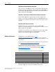
Supplemental Drive Information A-5 Carrier Frequency For Frame 2 drives, see the carrier frequency derating table below. PowerFlex 700L Frame 3A and 3B drives cannot be run above 4 kHz. 360 293 Amps (80%) Output (Amps) 0 8 6 2 4 Carrier Frequency (kHz) The following tables provide normal duty and heavy duty drive ratings (including continuous, 1 minute, and 3 second). Horsepower/Current Ratings Drive Catalog Number Frame Table A.A 400V AC Ratings (AC Input/AC Output) PWM Freq.
A-6 Supplemental Drive Information Drive Catalog Number Frame Table A.D 690V AC Ratings (AC Input/AC Output) PWM Freq. (kHz) 20LF380 3A 4 20LF705 3B 4 20LF1K0 (1) (2) 3B 2 (2) Output Power Output Current (with 690V AC Induction Motor) (1) HP (kW) Cont. 110% 1 min. 150% 3 secs. Cont. 150% 1 min. 200% 3 secs.
Supplemental Drive Information A-7 Circuit Breakers The “non-fuse” listings in the following tables include inverse time circuit breakers, instantaneous trip circuit breakers (motor circuit protectors), and 140M self-protected combination motor controllers. If one of these is chosen as the desired protection method, the following requirements apply. • IEC – Both types of circuit breakers and 140M self-protected combination motor controllers are acceptable for IEC installations.
A-8 Supplemental Drive Information Drive Catalog Number Frame Table A.I 650 Volt DC Input Fusing HP (kW) Rating DC Input Rating Bussmann Fuse ND Amps Amps Catalog No. 2000 170M6621 (2) 2000 170M6621 (2) HD 20LD650 3A 600 (445) 440 (325) 1250 20LD1K2 3B 1150 (860) 845 (630) 1250 (1) (2) (1) Only the Dual Inverter for PowerFlex 700L Frame 3A is available as a DC input inverter. Two 1000A Bussmann 170M6614 fuses per phase can also be used. Drive Catalog Number Frame Table A.
Appendix B Frame 2 Schematics The schematics on the following pages illustrate the PowerFlex 700L Frame 2 Liquid-Cooled drives.
B-2 Frame 2 Schematics Regenerative Drive Wiring Diagram with TB4 Connections – 400/480V, 3 Phase R4 - 47 ohms Magnetics 700L Fr2 - 3% Line Reactor 700L Fr2 - 9% Line Reactor Impedance Impedance L1 = 59 µH L2 = 178 µH 480V Three Phase A.C.
Frame 2 Schematics B-3 Three Phase A.C. Output Contactors Motor Shield 700L Fr2 - Contactor K2 RA# 100-d420ed11 Contactor K1 RA# 100-c60d10 U V CT Part # LEM: HAL 600-S CT Part # LEM: HAL 600-S M + M + M + CT1 CT2 CT3 T S R DC+ Test Point Each Cap (C6-C11) = 9,000 µF Cap Total = 13,500 µF +DC TB4(4b - 6) NTC 0.4 µF Conv. Snubber C9 C10 C11 TB4(4a - 7) C8 R8 - 15K M + CT4 CT5 CT6 U V W Inverter Snubber Temp Switch TB4(4b - 7) C7 M + TB4(4b - 8) 0.
B-4 Frame 2 Schematics Regenerative Drive Wiring Diagram without TB4 Connections – 400/480V, 3 Phase 480V Three Phase A.C.
Frame 2 Schematics Three Phase A.C. Output Contactors 700L Fr2 - Contactor K2 RA# 100-d420ed11 Contactor K1 RA# 100-c60d10 U V B-5 Motor Shield W 8 7 6 J1 80 W SMPS PCB (A07) CT Part # LEM: HAL 600-S M + M + CT1 M + CT2 T 4 J3 CT Part # LEM: HAL 600-S M + 1 DC- Test Point CT2 S Conv.
B-6 Frame 2 Schematics Notes: PowerFlex 700L Frames 2, 3A, and 3B Liquid-Cooled AC Drives User Manual Publication 20L-UM001E-EN-P
Appendix C Frame 3A and 3B Schematics Schematics on the following pages illustrate the PowerFlex 700L Frame 3A and Frame 3B Liquid-Cooled drives and power modules.
C-2 Frame 3A and 3B Schematics Frame 3A Regenerative Drive Wiring Diagram – 400/480V, 3 Phase Input Field Wiring Ref. L1 L2 1 RED 222B M1 WHT 2AB 2 5A/600V FU1 224A L3 GND T1 Control Transformer (1kVA, 120V, 8.5A) X1 221A 10A/600V FU3 H1 225A H* FU2 CB1 Main Breaker ST R S T 2 239A WHT 1 238A YEL 202B 201B 201A CA1 Filter Cap Assembly 32 µF ea.
Frame 3A and 3B Schematics C-3 FUSE TABLE - DRIVE INPUT NOTES: 1.) Dashed lines indicate external components and wiring by others. 318 317 300 N PE L1 M6 Power Module Bay Door 301 302 303 Ref.
C-4 Frame 3A and 3B Schematics Frame 3A Regenerative Drive Wiring Diagram – 600/690V, 3 Phase L1 L2 L3 T1 Control Transformer (1kVA, 120V, 8.5A) Input Field Wiring Ref.
Frame 3A and 3B Schematics C-5 FUSE TABLE - INPUT FILTER BAY Ref. FU1 FU2 FU3 FU4 FU5 FU6 FU7 FU8 FU9 FU10 FU11 FU12 NOTES: 1.) Dashed lines indicate external components and wiring by others.
C-6 Frame 3A and 3B Schematics Frame 3A Converter/Inverter Power Module Wiring Diagram – 400/690V, 3 Phase Converter IGBT Modules Option #2 - Lower Middle #1 - Bottom CT1 L1 Three Phase A.C.
Frame 3A and 3B Schematics For 600V and 690V Classes DC Bus Harness To Power Supply PCB J3 Inverter IGBT Modules Option #3 - Upper Middle #4 - Top 2 R3 1 C C R2 2 1 C C R1 2 1 C C U V N T C Three Phase A.C.
C-8 Frame 3A and 3B Schematics Frame 3A Dual Inverter Power Module Wiring Diagram – 400/690V, 3 Phase U Three Phase A.C.
Frame 3A and 3B Schematics Top Inverter IGBT Modules Option #3 - Upper Middle #4 - Top For 600V and 690V classes DC (+) DC Bus Harness To Power Supply PCB J3 DC (-) 2 R3 1 C C R2 2 1 C C R1 2 1 C C 2 1 2 R1 1 R2 U CT5 N T C For 400V and 480V Classes DC Bus Harness To Power Supply PCB J2 CT4 J1 C C C C N T C IGBT Interface PCB J2 J3 J4 IGBT Interface Harness Temp. Sense Harness Three Phase A.C.
C-10 Frame 3A and 3B Schematics Frame 3B Regenerative Drive Wiring Diagram – 400/480V, 3 Phase L1 L2 L3 5A/600V FU1 224A TB1 1 225A 2 * 3 FU2 4 5 GND CB1 Main Breaker ST R S T 2 239A WHT 238A YEL 1 202B 201B 201A FU8 FU9 2 1 300A 600V 32 µF ea.
Frame 3A and 3B Schematics C-11 FUSE TABLE - DRIVE INPUT NOTES: 1.) Dashed lines indicate external components and wiring by others. 318 317 300 N PE L1 M6 Power Module Bay Door Ref.
C-12 Frame 3A and 3B Schematics Frame 3B Regenerative Drive Wiring Diagram – 600/690V, 3 Phase L1 L2 L3 2 6A/690V FU1 224A TB1 1 2 3 225A 4 * 5 FU2 1 239A WHT 238A YEL GND CB1 Main Breaker ST R S T 202B 201B 201A 32 µF ea.
Frame 3A and 3B Schematics C-13 FUSE TABLE - INPUT FILTER BAY NOTES: 1.) Dashed lines indicate external components and wiring by others. 318 317 300 N PE L1 M6 Power Module Bay Door 222A 301 302 303 L1 L2 L3 Ref.
C-14 Frame 3A and 3B Schematics Frame 3B Active Converter Power Module Schematic – 400/690V, 3 Phase Converter IGBT Modules Option CT1 #1 - Bottom L1 #2 - Lower Middle CT2 Three Phase A.C.
Frame 3A and 3B Schematics Converter IGBT Modules Option #3 - Upper Middle For 600V and 690V Classes #4 - Top DC (+) R3 N T C DC Bus Harness To Power Supply PCB J3 N T C IGBT Interface PCB J2 J3 J1 J4 J1 C-15 R2 R1 IGBT Interface PCB J2 J3 2 C C C C C C 1 2 DC Output to Inverter Power Module 1 2 1 DC (-) For 400V and 480V Classes J4 DC Bus Harness To Power Supply PCB J2 R2 R1 2 C C 1 2 C C 1 Temp.
C-16 Frame 3A and 3B Schematics Frame 3B Inverter Power Module Schematic – 400/690V, 3 Phase Inverter IGBT Modules Option For 600V and 690V Classes #1 - Bottom DC (+) To Power Supply PCB J3 DC Input from Converter Power Module R3 2 1 C C R2 2 1 C C R1 2 1 C C #2 - Lower Middle N T C N T C DC (-) For 400V and 480V Classes J1 2 C R2 1 2 C R1 1 To Power Supply PCB J2 IGBT Interface PCB J2 J3 J4 J1 IGBT Interface PCB J2 J3 C C Chassis DC Bus Input DC (+) Testpoint DC (-) Testpoin
Frame 3A and 3B Schematics C-17 Inverter IGBT Modules Option #3 - Upper Middle CT1 #4 - Top U CT2 N T C N T C IGBT Interface PCB J1 J2 J3 CT3 IGBT Interface PCB J1 J2 J3 J4 V Three Phase A.C. Output W J4 Motor Shield PE Motor Ground PE Earth Ground Chillplate NTC W Gate J6 V Gate J5 U Gate J4 Inverter Rating Plug PCB Option J5 Voltage Feedback PCB (PF 700S Ph.
C-18 Frame 3A and 3B Schematics Notes: PowerFlex 700L Frames 2, 3A, and 3B Liquid-Cooled AC Drives User Manual Publication 20L-UM001E-EN-P
Index Numerics 700 Active Converter (regenerative drive only) removing control cassette Frame 2, 2-7 Frame 3A, 3-13 Frame 3B, 3-13 active converter (regenerative drive only) information reference, P-1 removing control cassette Frame 2, 2-7 Frame 3A, 3-13 Frame 3B, 3-13 agency certification, A-1 700 Vector Control (standard) fault descriptions, 6-5 information reference, P-1 removing control cassette Frame 2, 2-8 Frames 3A and 3B, 3-14 air flow clearance requirements Frame 2, 2-2 Frames 3A and 3B, 3-2, 3-
Index-2 communication adapter information reference, P-2 Communication File (700 Vector Control), 5-3 components for Frame 3A and 3B drives, 3-1 contactors - input/output, 1-9 control synchronization cable connections Frame 2, 2-20 Frame 3A, 3-34 Frame 3B, 3-36 control terminal block wire sizes Frame 2, 2-18 Frames 3A and 3B, 3-31 conventions used in this manual, P-3 coolant biocide treatment, 4-11 connections to Frame 2 drive or Frame 3A or 3B power module, 4-7 Frame 3A or 3B complete drive, 4-8 corrosion
Index-3 G L general precautions, P-4 lifting complete drive Frame 2, 2-3 Frames 3A and 3B, 3-8 input filter bay (Frames 3A and 3B), 3-10 power module (Frames 3A and 3B), 3-11 grounding the power module Frame 2, 2-11 Frames 3A and 3B, 3-22 Group - Parameter 700 Vector Control Alarms, 5-2 Comm Control, 5-3 Diagnostic, 5-1 Masks & Owners, 5-3 Security Status, 5-4 Local Mask parameter (700 Vector Control), 5-3 Local Owner parameter (700 Vector Control), 5-4 Logic Mask Act parameter (700 Vector Control), 5
Index-4 P Parameters 700 Vector Control Accel Mask, 5-3 Accel Owner, 5-4 Alarm 1 @ Fault, 5-2 Alarm Config 1, 5-2 Decel Mask, 5-3 Decel Owner, 5-4 Direction Mask, 5-3 Direction Owner, 5-4 DPI Port Sel, 5-3 Drive Alarm 1, 5-1 Fault Clr Mask, 5-3 Fault Clr Owner, 5-4 Jog Mask, 5-3 Jog Owner, 5-3 Local Mask, 5-3 Local Owner, 5-4 Logic Mask, 5-3 Logic Mask Act, 5-4 MOP Mask, 5-3 MOP Owner, 5-4 Port Mask Act, 5-4 Reference Mask, 5-3 Reference Owner, 5-4 Start Mask, 5-3 Start Owner, 5-3 Stop Owner, 5-3 Write Mas
Index-5 V specifications agency certification, A-1 control, A-2 electrical, A-2 environment, A-2 protection, A-1 Vector Control (standard) removing control cassette Frame 2, 2-8 Frames 3A and 3B, 3-14 stand-alone inverter power modules (Frame 3B only), 3-35 Start Mask parameter (700 Vector Control), 5-3 Start Owner parameter (700 Vector Control), 5-3 start/stop - repeated, 1-9 static discharge (ESD), P-4 status indicators accessing on powered Frame 3A and 3B complete drive, 6-2 descriptions of indicatio
Index-6 PowerFlex 700L Frames 2, 3A, and 3B Liquid-Cooled AC Drives User Manual Publication 20L-UM001E-EN-P
U.S. Allen-Bradley Drives Technical Support - Tel: (1) 262.512.8176, Fax: (1) 262.512.2222, Email: support@drives.ra.rockwell.com, Online: www.ab.com/support/abdrives www.rockwellautomation.com Power, Control and Information Solutions Headquarters Americas: Rockwell Automation, 1201 South Second Street, Milwaukee, WI 53204-2496 USA, Tel: (1) 414.382.2000, Fax: (1) 414.382.