
Instruction Manual

www.rockwellautomation.com
Amer
i
cas:
Rockwell
Automation, 1201 South
Second
Street,
Milwaukee,
WI 53204
-
2496
USA,
Tel:
(1)
414.382.2000, Fax: (1)
414.382.4444
Europe
/
Middle East
/
Africa:
Rockwell
Automati
on,
Pegasus
Park,
De Kleetlaan 12a,
1831 Diegem, Belgium,
Tel: (32) 2 663
0600, Fax: (32) 2 663
0640
Asia Pacific: Rockwell Automation, Level 14,
Core F,
Cyberport
3, 100
Cyberport Road,
Hong Kong,
Tel: (852) 2887 4788, Fax:
(852) 2508
1846
Power,
Control
and
Information Solutions
Headquarters
U.S. Allen-Bradley Drives Technical Support - Tel: (1) 262.512.8176, Fax: (1) 262.512.2222, Email: support@drives.ra.rockwell.com, Online: www.ab.com/support/abdrives
Publication 20L-IN004A-EN-P – September, 2006 P/N 181694-P01
Copyright © 2006 Rockwell Automation, Inc. All rights reserved. Printed in USA.
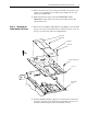
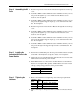
Step 7: Installing the
Shields
1. Align six (6) holes in the Front Shield with holes in the top cover and
assemble six (6) plastic rivets. Apply force with the malleable hammer
as required to completely install the plastic rivets.
2. Align five (5) holes in the Rear Shield with holes in the top cover and
assemble five (5) plastic rivets. Apply force with malleable hammer as
required to completely install the plastic rivets.
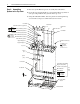
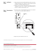
Step 8: Documenting the
Change
1. Record the change on the Field Installed Option label. Use a marker to
write in the kit catalog number (SK-L1-DCBS1-F3).
2. Replace the power module lower front cover.
DANGER
PORT
POWER
STS
MOD
NET A
NET B
FIELD INSTALLED OPTIONS
Firmware #: Date
Firmware
20-HIM
28-IO-
20-COMM-
20B_-DB1-
HIM
I/O
COM Module
Internal Dynamic Brake
#: Date
Power Module
Lower Front Cover
Cutaway