
Instruction Manual

2 PowerFlex® 700L Frame 3A DC Bus Bar Conversion Kit
What You Need to Do
To install the PowerFlex
®
700L Frame 3A Power Module DC Bus Bar
Conversion Kit:
❐ Step 1: Remove power from the power module
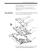
❐ Step 2: Remove the power module top cover
❐ Step 3: Assemble spacers to the top cover
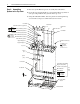
❐ Step 4: Assemble the kit parts
❐ Step 5: Install assembled kit parts to the power module
❐ Step 6: Tighten fasteners
❐ Step 7: Install shields
❐ Step 8: Document change
Step 1: Removing Power
from the Power Module
1. Turn off and lock out input power. Wait 5 minutes.
2. Verify that there is no voltage at the power module’s input power
terminals.
!
ATTENTION: To avoid an electric shock hazard, verify that the
voltage on the bus capacitors has completely discharged before
performing any work on the power module. After removing
power to the power module, wait 5 minutes for the bus capacitors
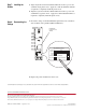
to discharge. Remove the lower front cover of the power module.
Measure the DC bus voltage at the DC+ TESTPOINT and DC-
TESTPOINT sockets on the front of the power module. The
voltage must be zero.
Remove power before making or breaking cable connections.
When you remove or insert a cable connector with power
applied, an electrical arc may occur, which can cause personal
injury or property damage by:
• sending an erroneous signal to your system’s field devices,
causing unintended machine motion
• causing an explosion in a hazardous environment
Electrical arcing causes excessive wear to contacts on both the
module and its mating connector. Worn contacts may create
electrical resistance.
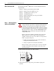
L1 L2 L3
O
I