
Instruction Manual

Installation Instructions
PowerFlex
®
700L Frame 3A DC Bus Bar
Conversion Kit
What This Kit Includes
• DC Bus bar spacers and plastic rivets
• DC- Bus bar and hardware
• DC+ Bus bar and hardware
• Bus bar Support Angles and hardware
• Front Shield and plastic rivets
• Rear Shield and plastic rivets
• Torque Seal
Tools That You Need
• Phillips
®
screwdriver (#2)
• Standard flat tip screwdriver
• Malleable hammer
• 10 mm socket
• 13 mm socket
• Socket wrench
• Torque wrench
• Pliers
Phillips
®
is a registered trademarks of Phillips Screw Company.
!
ATTENTION: To avoid an electric shock hazard, ensure that all
power to the power module has been removed before performing
any steps of these instructions.
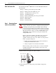
!
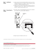
ATTENTION: To avoid an electric shock hazard, verify that the
voltage on the bus capacitors has completely discharged before
performing any work on the power module. After removing
power to the power module, wait 5 minutes for the bus capacitors
to discharge. Remove the lower front cover of the power module.
Measure the DC bus voltage at the DC+ TESTPOINT and DC-
TESTPOINT sockets on the front of the power module. The
voltage must be zero.
!
ATTENTION: HOT surfaces can cause severe burns. Do not
touch the heatsink surface during operation of the power module.
After disconnecting power allow time for cooling.
!
ATTENTION: This power module contains ESD (Electrostatic
Discharge) sensitive parts and assemblies. Static control
precautions are required when installing, testing, servicing or
repairing this assembly. Component damage may result if ESD
control procedures are not followed. If you are not familiar with
static control procedures, refer to Allen-Bradley publication
8000-4.5.2, “Guarding Against Electrostatic Damage” or any
other applicable ESD protection handbook.