
Owner's manual

PowerFlex 700L Frame 1X Drive Installation Instructions – Publication 20L-IN013A-EN-P – June 2009
8
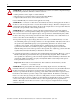
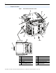
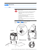
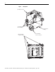
Figure 1 Frame 1X Drive Component Locations
Component Locations
R
➊
➏
➐
S
T
➋
➍
➍
➒
➍
➓
➎
➌
FRONT
➑
LEFT SIDE VIEW
➒
Back
OUTPUT
U
T1
V
T2
W
T3
U
T1
V
T2
W
T3
OUTPUT
Item Component Item Component
➊
Input Power Terminal Connections
➏
Main Control Board
➋
Output Power Terminal Connections
➐
RTD PC Board
➌
Brake Resistor Connections
➑
Cooling Loop Connections
➍
PE Grounds
➒
DC+ and DC- Test Pt. Sockets
➎
Access Point for Common Mode
Capacitor and MOV Connections
➓
Drive Data Nameplate