
Owner's manual

PowerFlex 700L Frame 1X Drive Installation Instructions – Publication 20L-IN013A-EN-P – June 2009
44
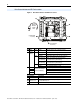
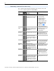
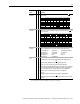
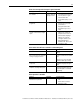
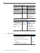
Figure 19 Drive Status Indicators and DPI Port Locations
Drive Status Indicators and DPI Port Locations
No. Name Color State Description
➊
PWR
(Power)
Green Steady Illuminates when power is applied to the drive.
➋
STS
(Status)
Green Flashing Drive ready, but not running and no faults are present.
Steady Drive running, no faults are present.
Yellow Flashing,
Drive Stopped
A start inhibit condition exists, the drive cannot be
started. Check Parameter 214 [Start Inhibits].
Flashing,
Drive Running
An intermittent type 1 alarm condition is occurring.
Check Parameter 211 [Drive Alarm 1].
Steady,
Drive Running
A continuous type 1 alarm condition exists.
Check Parameter 211 [Drive Alarm 1].
Red Flashing Fault has occurred. Check [Fault x Code] or Fault Queue.
Steady A non-resettable fault has occurred.
➌
PORT Optional
Communication Adapter
(refer to User Manual)
Status of DPI port internal communications (if present).
MOD Status of communications module (when installed).
NET A Status of network (if connected).
NET B Status of secondary network (if connected).
No. Connector Description
➍
DPI Port 2 Cable connection for handheld and remote options.
➎
DPI Port 3 or 2
1203-S03 splitter cable (purchased separately) connected to DPI Port 2
provides additional port.
➏
DPI Port 5 Cable connection for optional communications adapter.
➍
➌
➋
➏
➊
T
BR1
S
R
➎
(located behind
cross brace)
(located behind
cross brace)
Optional
1203-S03
Splitter
Cable