
Owner's manual


PowerFlex 700L Frame 1X Drive Installation Instructions – Publication 20L-IN013A-EN-P – June 2009
29
By default, the user can program a digital input as an Enable input. The
status of this input is interpreted by drive software. If the application
requires the drive to be disabled without software interpretation, a
“dedicated” hardware enable configuration can be used. This is done by
removing a jumper and wiring the enable input to “Digital In 6.”
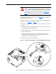
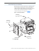
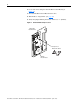
1. Remove the drive Main Control Board (see Figure 11
).
Figure 11 Main Control Board Removal
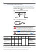
Hardware Enable Circuitry (Vector Control Only)
U
T1
U
V
W
V
T2
OUTPUT
W
T3
BR2 BR1
T
S
R
Flathead Screw
M4 x 12 mm Long
2X (apply Loctite to threads)
1.9 N•m (17 lb•in)
Flathead Screw
M4 x 10 mm Long
2X
1.9 N•m (17 lb•in)
Flathead Screw
M4 x 10 mm Long
1X
1.9 N•m (17 lb•in)
Flathead Screw
M4 x 10 mm Long
4X
1.9 N•m (17 lb•in)