
Owner's manual


PowerFlex 700L Frame 1X Drive Installation Instructions – Publication 20L-IN013A-EN-P – June 2009
28
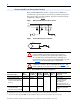
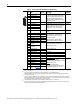
3-Wire Control
Internal supply
• No changes required if parameters
are at factory default settings
3-Wire Control
External supply (I/O Board
dependent). Requires 3-wire
functions only ([Digital In1
Sel]). Using 2-wire selections
will cause a type 2 alarm.
• No changes required if parameters
are at factory default settings
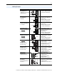
Digital Input
PLC Output Card (Board
dependent). Resistors are
recommended to dissipate
leakage current.
• No changes required if parameters
are at factory default settings
Digital Output
Relays shown in powered
state with drive faulted. See
Table 9
.
Vector Control:
2 relays at terminal 14…16
Standard Control:
1 relay at terminals 14…16
Vector Control:
• Select Source to Activate:
Parameters 380/384/388
Standard Control:
• Select Source to Activate:
Parameters 380/384
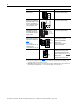
Enable Input Vector Control
• Configure with Parameter 366.
For dedicated hardware Enable:
Remove Jumper J10 (see page 30
)
Standard Control:
• Configure with Parameter 366
(1)
Refer to the Attention statements on page 24 for important bipolar wiring information.
(2)
A PTC (Positive Temperature Coefficient) device (motor thermistor), embedded in the motor windings, can be
monitored by the drive for motor thermal protection.
(3)
Important: Programming inputs for 2 wire control (Run) deactivates all HIM Start buttons unless Parameter 192
[Save HIM Ref], bit 1 (Manual Mode) = “1.” This will allow the HIM to control Start and Jog.
Input/Output Connection Example Required Parameter Changes
Start
24
25
26
27
28
Stop
Start
25
27
28
Stop
115V
/
+24V
Neutral/
Common
25
27
28
Control from
Prog. Controller
Neutral/
Common
10k Ohm, 2 Watt
Power Source
11
12
13
14
15
16
Fault
NOT Fault
NOT Run
Run
or
32