
Owner's manual


PowerFlex 700L Frame 1X Drive Installation Instructions – Publication 20L-IN013A-EN-P – June 2009
25
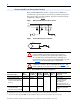
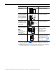
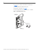
Figure 10 shows the drive Main Control Board and its terminal block
locations. The Main Control Board includes the drive control firmware, I/O
terminal block, and optional encoder board.
Figure 10 Drive Main Control Board and I/O Control Terminal Blocks
Table 8 I/O Terminal Block Specifications
I/O Terminals
T
➋➊
BR1
S
R
Pin 1
Main Control Board
Terminal Details
Pin 1
No. Name Description
Wire Size Range
(1)
(1)
Maximum/minimum that the terminal block will accept - these are not recommendations.
Torque
Maximum Minimum Maximum Recommended
➊
I/O Terminal Block Signal and control
connections
2.1 mm
2
(14 AWG)
0.30 mm
2
(22 AWG)
0.6 N•m
(5.2 lb•in)
0.6 N•m
(5.2 lb•in)
➋
Encoder (optional)
Ter minal Block
Encoder power and
signal connections
0.75 mm
2
(18 AWG)
0.196 mm
2
(24 AWG)
0.6 N•m
(5.2 lb•in)
0.6 N•m
(5.2 lb•in)