
Owner's manual

PowerFlex 700L Frame 1X Drive Installation Instructions – Publication 20L-IN013A-EN-P – June 2009
19
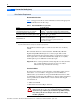
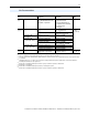
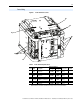
Figure 6 Power Terminal Locations
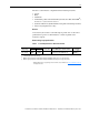
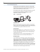
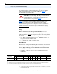
Table 5 Power Terminal Specifications
Power Wiring
R
➊
S
T
➋
➍
➍
➍
➌
U
T1
V
T2
W
T3
OUTPUT
Item Name Description
Wire Size Range
(1)
(1)
Maximum/minimum sizes that the terminal block will accept - these are not recommendations.
Recommended
Torque (±10%)
Terminal
Bolt SizeMaximum Minimum
➊
Input
Power
R (L1), S (L2), and T (L3)
connections
70 mm
2
(2/0 AWG)
50 mm
2
(1 AWG)
7.9 N•m
(70 lb•in)
M6
➋
Output
Power
U (T1), V (T2), and W (T3)
connections
70 mm
2
(2/0 AWG)
50 mm
2
(1 AWG)
3.95 N•m
(35 lb•in)
M5
➌
Brake
Resistor
BR1 (DC Brake +) and BR2
(DC Brake -) connections
35 mm
2
(2 AWG)
25 mm
2
(4 AWG)
3.95 N•m
(35 lb•in)
M5
➍
Ground PE and motor ground
connections
70 mm
2
(2/0 AWG)
50 mm
2
(1 AWG)
7.9 N•m
(70 lb•in)
M6