Installation Instructions PowerFlex® 700L Frame 1X Liquid-Cooled Adjustable Frequency AC Drive Introduction When reading this document, look for this symbol “ Step x ” to guide you through the 6 BASIC STEPS needed to install and perform a Basic Start-Up of the PowerFlex 700L Frame 1X drive. A Human Interface Module (HIM) is required to perform the Basic Start-Up routine covered in this document. The information provided is intended for qualified drive service personnel only.
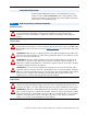
Table of Contents Catalog Number Explanation. . . . . . . . . . . . . . . . . . . . . . . . . . . . . . . . . . . . . . . 3 Step 1 Read the Precautions and General Information. . . . . . . . . . . . . . . . . . . . . . . . 3 CE Conformity . . . . . . . . . . . . . . . . . . . . . . . . . . . . . . . . . . . . . . . . . . . . . . . . . . . 5 Component Locations. . . . . . . . . . . . . . . . . . . . . . . . . . . . . . . . . . . . . . . . . . . . . . 8 Step 2 Mount the Drive. . . . . . . . . . . . . .
Catalog Number Explanation Each PowerFlex 700L Frame 1X drive can be identified by its catalog number, which is CNMD180W0ENNNC1. The catalog number is on the shipping label and drive data nameplate. The catalog number includes the drive and any factory-installed options.
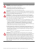
! ATTENTION: An incorrectly applied or installed bypass system can result in component damage or reduction in product life. The most common causes are: • Wiring AC line to drive output or control terminals. • Improper bypass or output circuits not approved by Allen-Bradley. • Output circuits which do not connect directly to the motor. Contact Allen-Bradley for assistance with application or wiring.
CE Conformity Compliance with the Low Voltage Directive and Electromagnetic Compatibility Directive has been demonstrated using harmonized European Norm (EN) standards published in the Official Journal of the European Communities. PowerFlex 700L drives, including Frame 1X, comply with the EN standards listed below when installed according to this PowerFlex 700L Frame 1X Liquid-Cooled Adjustable Frequency AC Drive Installation Instructions. CE Declarations of Conformity are available online at: www.
• The PowerFlex 700L Frame 1X drive generates harmonic current emissions on the AC supply system. When operated on a public network it is the responsibility of the installer or user to ensure that applicable requirements of the distribution network operator have been met. Consultation with the network operator and Rockwell Automation may be necessary.
Installation Requirements Related to EN 61800-3 and the EMC Directive • The drive must be earthed (grounded) as described in these instructions (see General Grounding Requirements on page 18). • Output power wiring to the motor must employ cable with a braided shield providing 75% or greater coverage, or the cables must be housed in metal conduit, or equivalent shielding must be provided. Continuous shielding must be provided from the drive enclosure to the motor enclosure.
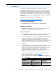
Component Locations Figure 1 Frame 1X Drive Component Locations ➎ ➍ ➓ ➌ ➍ W T3 ➊ R OUTPUT V T2 ➒ U T1 S T ➋ ➍ ➏ ➐ ➒ LEFT SIDE VIEW FRONT U T1 V T2 Back OUTPUT W T3 ➑ Item Component ➊ Input Power Terminal Connections Item Component ➏ Main Control Board ➋ ➌ ➍ ➎ ➐ ➑ ➒ RTD PC Board ➓ Drive Data Nameplate Output Power Terminal Connections Brake Resistor Connections PE Grounds Access Point for Common Mode Capacitor and MOV Connections Cooling Loop Connections DC+ and DC- Test Pt.
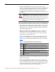
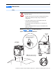
Step 2 Mount the Drive Lifting ATTENTION: To guard against possible personal injury and/or equipment damage... ! • Do Not allow any part of the drive or lifting mechanism to make contact with electrically charged conductors or components. • At no time should a person or their limbs be directly underneath the items being lifted. • Do not subject the load to high rates of acceleration or deceleration. • Inspect all lifting hardware for proper attachment before lifting drive unit.
Figure 3 Lifting Details Use handles to lift unit. T TPU OU U T1 V T2 W T3 Do not lift unit by holes in coldplate. Use unit cutouts for lifting. Do not lift unit by holes in coolant port. T S R Do not use holes in coldplate for lifting.
Mounting Considerations This drive is intended to be installed in an enclosure by sliding it in on the white Teflon® sliders. These sliders should slide into rails inside the enclosure so that the drive cannot move from side to side. Operating Temperatures PowerFlex 700L Frame 1X drives are designed to operate at -10…60 °C (14…140 °F) ambient. Minimum Mounting Clearances and Heat Dissipation There is no minimum mounting clearance required for the drive to dissipate heat.
Step 3 Connect the Cooling Loop Drive Coolant Requirements Recommended Coolants Table 3 lists approved sources and recommended coolants with appropriate corrosion inhibitors for the drive loop: Table 3 Recommended Drive Loop Coolants Source Interstate Chemical http://www.interstatechemical.com/contact.
The drive coolant must be compatible with the following materials: • • • • Copper Brass Aluminum Arimid fiber gasket with nitrile binder (Garlock, Inc. Blue-Gard 3000®) Blue-Gard 3000 is a registered trademark of Garlock, Inc. • Synthetic rubber hose (Parker Hannifan Corp 801 General Purpose Hose) • Viton seal (Complete Drive only) Biocide A biocide may be needed to control biological growth. Use of a biocide is permitted. For specific recommendations, consult a reputable water treatment company.
Cooling Loop Application Guidelines ! ATTENTION: Risk of equipment damage exists. Do not use ferrous and plated-ferrous materials for pipe-treated water to the power modules and drive. Use of ferrous materials will degrade the performance of the power module chillplate. The following section is intended to provide guidelines for applying cooling loops other than those recommended. 1. The allowable drive coolant temperature range is 0…60 °C (32…140 °F).
Drive Coolant Connections For locations of the coolant inlet and outlet connections on PowerFlex 700L Liquid-Cooled Frame 1X drives, refer to item 8 in Figure 1 on page 8. The rated working pressure of the Frame 1X drive is 6.89 bar (100 psi). Coolant supply and return lines should be sized for 76 LPM (20 GPM) / 6.89 bar (100 psi) service with a maximum operating temperature of 60 °C (140 °F). The required operating flow rate and pressure drop is specified in Table 4 on page 13.
Grounding Guidelines for PWM AC Drives (publication DRIVES-IN001) for more information on impedance grounded and ungrounded systems. ! ATTENTION: The PowerFlex 700L Frame 1X drive contains protective MOVs and common mode capacitors that are referenced to ground. To guard against drive damage, these devices must be disconnected if the drive is installed on an ungrounded, impedance or phase-grounded distribution system. See Table 7 on page 22 for recommended jumper configurations.
Wire Recommendations Type Power Standard Signal Standard Analog I/O (1)(2) (1) (3) (4) Encoder/Pulse I/O: <30 m (100 ft.) Encoder/Pulse I/O: 30…152 m (100…500 ft.) Wire Type(s) Description 600V, 90 °C (194 °F) XHHW2/RHW-2 • Four tinned copper conductors with XLPE insulation. Anixter B209500-B209507, Belden 29501-29507, or equivalent • Copper braid/aluminum foil combination shield and tinned copper drain wire. • PVC jacket. Belden 8760/9460 (or equivalent) 0.
General Grounding Requirements The drive Safety Ground - PE must be connected to system ground. Ground impedance must conform to the requirements of national and local industrial safety regulations and/or electrical codes. The integrity of all ground connections should be periodically checked. For installations within a cabinet, a single safety ground point or ground bus bar connected directly to building steel should be used.
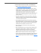
Power Wiring Figure 6 Power Terminal Locations ➍ ➌ ➍ W T3 ➊ OUTPUT V T2 R U T1 S T ➋ ➍ Table 5 Power Terminal Specifications Wire Size Range (1) Maximum Minimum 70 mm2 50 mm2 (2/0 AWG) (1 AWG) Item Name ➊ Input Power Description R (L1), S (L2), and T (L3) connections ➋ Output Power U (T1), V (T2), and W (T3) 70 mm2 connections (2/0 AWG) ➌ Brake BR1 (DC Brake +) and BR2 35 mm2 Resistor (DC Brake -) connections (2 AWG) ➍ Ground (1) PE and motor ground connections 70 mm2 (2/0 AWG
Drive, Fuse, and Circuit Breaker Ratings The PowerFlex 700L Frame 1X drive includes input fuses. National and local industrial safety regulations and/or electrical codes may determine additional requirements for these installations. Refer to Table 6 for recommended fuses/circuit breakers. ! ATTENTION: The PowerFlex 700L Frame 1X drive does not provide branch short circuit protection.
Using Input/Output Contactors Input Contactor Precautions ! ! ATTENTION: A contactor or other device that routinely disconnects and reapplies the AC line to the drive to start and stop the motor can cause drive hardware damage. The drive is designed to use control input signals that will start and stop the motor. If an input device is used, operation must not exceed one cycle per minute or drive damage will occur.
Disconnecting MOVs and Common Mode Capacitors The PowerFlex 700L Frame 1X drive contains protective MOVs and common mode capacitors that are referenced to ground. To guard against drive damage and/or operation problems, these devices must be properly configured according to Table 7.
! ATTENTION: To avoid an electric shock hazard, verify that the voltage on the bus capacitors has discharged before connecting/ disconnecting the MOV, EMI Snubber Board, and common mode capacitor wires. Measure the DC bus voltage at the DC+ and DC– Test Pt. sockets on the drive (see item 9 in Figure 1 on page 8 for location). The voltage must be zero. The power jumpers PE-A, PE-C, PE-D, and PE-E are factory connected to ground using one of the two screws shown in Figure 9.
Step 5 I/O Wiring Important points to remember about I/O wiring: • Use Copper wire only. Wire gauge requirements and recommendations are based on 75 °C (167 °F). Do not reduce wire gauge when using higher temperature wire. • Wire with an insulation rating of 600V or greater is recommended. • Control and signal wires should be separated from power wires by at least 0.3 meters (1 foot).
I/O Terminals Figure 10 shows the drive Main Control Board and its terminal block locations. The Main Control Board includes the drive control firmware, I/O terminal block, and optional encoder board. Figure 10 Drive Main Control Board and I/O Control Terminal Blocks Pin 1 Pin 1 T S R BR1 Main Control Board Terminal Details ➊ ➋ Table 8 I/O Terminal Block Specifications Wire Size Range (1) Maximum Minimum No. Name Description ➊ I/O Terminal Block Signal and control 2.1 mm2 0.
Table 9 1 16 (1) (2) (3) (4) (5) (6) 32 Vector Control Option I/O Terminal Designations No. 1 2 3 4 Signal Analog In 1 (–) (1) Analog In 1 (+) (1) Analog In 2 (–) (1) Analog In 2 (+) (1) 5 6 7 8 9 10 Pot Common Analog Out 1 (–) Analog Out 1 (+) Analog Out 2 (–) Analog Out 2 (+) HW PTC Input 1 11 12 13 14 15 16 17 18 19 20 21 22 23 24 25 26 27 28 29 30 31 32 Digital Out 1 – N.C. (4) Digital Out 1 Common Digital Out 1 – N.O. (4) Digital Out 2 – N.C. (4) Digital Out 2/3 Com. Digital Out 3 – N.
I/O Wiring Examples Input/Output Connection Example Potentiometer Unipolar Speed Reference (1) 10k Ohm Pot.
Input/Output 3-Wire Control Internal supply Connection Example 24 25 26 27 28 Required Parameter Changes • No changes required if parameters are at factory default settings Stop Start 3-Wire Control External supply (I/O Board dependent). Requires 3-wire functions only ([Digital In1 Sel]). Using 2-wire selections will cause a type 2 alarm.
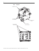
Hardware Enable Circuitry (Vector Control Only) By default, the user can program a digital input as an Enable input. The status of this input is interpreted by drive software. If the application requires the drive to be disabled without software interpretation, a “dedicated” hardware enable configuration can be used. This is done by removing a jumper and wiring the enable input to “Digital In 6.” 1. Remove the drive Main Control Board (see Figure 11).
2. Locate and remove Jumper J10 on the Main Control Board (see Figure 12). 3. Re-install the Main Control Board into the drive. 4. Wire Enable to “Digital In 6” (see page 26). 5. Verify that [Digital In6 Sel], Parameter 366 is set to “1” (Enable).
Encoder Interface Option (Vector Control Only) Table 10 Encoder Terminal Designations No. See “Detail” in 8 Figure 10 7 6 5 8 4 3 2 1 1 (1) (2) Description +12V (1) DC Power +12V (1) DC Return (Common) Encoder Z (NOT) Encoder Z Encoder B (NOT) Encoder B Encoder A (NOT) Encoder A Internal power source 250 mA. Pulse, marker or registration input. (2) Quadrature B input. Single channel or quadrature A input. Jumper selectable +5/12V is available on 20B-ENC-1 Encoder Boards.
Figure 14 Sample Encoder Wiring I/O Encoder Power – Internal Drive Power Internal (drive) 12V DC, 250 mA (1) Connection Example +12V DC (250 mA) 8 7 Common 6 5 to SHLD (1) 4 3 2 1 Encoder Signal – Single-Ended, Dual Channel (2) to Power Supply Common 8 7 Z NOT 6 5 to SHLD (1) Z B NOT 4 3 2 1 B A NOT A + Common Encoder Power – External Power Source to SHLD (1) External Power Supply Encoder Signal – Differential, Dual Channel 8 to SHLD 7 6 5 4 3 2 1 (1) (2) Z NOT Z B NOT B A NOT
Resistance Temperature Detector (RTD) Board Up to eight RTD or NTC (negative temperature coefficient) temperature sensors are supported by the RTD board in the PowerFlex 700L Frame 1X drive. The number of I/O connections required from an upper level controller to use the RTD board can be managed by selecting one of several configuration options.
Table 12 J2 RTD Board I/O Function Settings J2 Position 1 2 3 4 5 6 7 8 9 10 11 12 I/O Function +24V COM LOUT1 COM LOUT2 COM LOUT3 COM LIN COM AOUT COM +24VDC LOUT1 NO LOUT2 NO LOUT3 NO LIN AOUT Important: A motor temperature sensor (RTD, NTC or thermocouple) should be considered equivalent to a motor thermostat and wired with the same considerations. Motor thermostat contacts are generally not isolated from the drive/controller digital inputs.
2. Determine the maximum voltage across RMAX using the following equation: VMAX = 1.00V x RMAX / (RMAX + 998) 3. Select the largest gain that results in VMAX * Gain (x10, x20, or x40), being less than 10 volts. Example: Using a 100 Ohm Pt RTD (a = 0.00385) to measure temperatures from 0…200 °C, the maximum resistance occurs at 200 °C and is approximately 177 Ohm. The maximum voltage across the sensor is 151 mV. If the x40 gain is used, the output voltage at 200 °C is 6.04 Volts.
When the “Mode” switch is up (open) the board uses the digital input as an enable/reset. When the board’s digital input is inactive (open or ground), the analog output is held at the first channel. When the digital input is active (24V), the microcontroller sequentially cycles through the eight temperature sensor channels. Each channel is available at the analog output for the selected period of time. After the eighth channel is completed, the cycle begins again with the first channel.
Step 6 Start-Up Check List • This check list supports the Basic Start-Up menu option. See page 41 for information on other start-up routines. • A Human Interface Module (HIM) is required to run the Basic Start-Up routine. • The Basic Start-Up routine may modify parameter values for Analog and Digital I/O. Refer to Common I/O Programming Changes on page 45. ! ATTENTION: Power must be applied to the drive to perform the following start-up procedure.
❏ 7. Press the Enter key to display the Start-Up Menu. ❏ 8. Use the Arrow keys to highlight “2. Basic”. ❏ 9. Press the Enter key. Follow the menu using the Enter key which will step you through the Start-Up routine. The Basic Start-Up routine asks simple questions and prompts you to input required information. See also Common I/O Programming Changes on page 45.
First Powerup Menu Structure English? Français? Español? Italiano? Deutsch? Português? Nederlands? Not Selected Main Menu: Diagnostics Parameter Device Select Memory Storage Start-Up Preferences PowerFlex 700 Start-Up Startup consists of several steps to configure a drive for basic applications. PowerFlex 700 Start-Up Make a selection: 1. SMART 2. Basic 3. Detailed 4. More info PowerFlex 700 Start-Up Complete these steps in order: 1. Motor Control 2. Motr Data/Ramp 3. Motor Tests 4. Speed Limits 5.
Human Interface Module (HIM) Overview LCD Display Elements Display Description F-> Power Loss Auto 0.0 Hz Main Menu: Diagnostics Parameter Device Select Direction⎥ Drive Status⎥ Alarm⎥ Auto/Man⎥ Information Commanded or Output Frequency Programming / Monitoring / Troubleshooting Human Interface Module (HIM) Key Functions Key Esc Sel Description Exit a menu, cancel a change to a parameter value, or acknowledge a fault/alarm. Select a digit, select a bit, or enter edit mode in a parameter screen.
ALT Functions To use an ALT function, start at the Main Menu and press the ALT key, release it, then press the programming key associated with one of the following functions: ALT Key…then Esc Esc Sel ALT Sel Function S.M.A.R.T. Log In/Out View Device Lang Auto/Man Remove +/– Param # Function Description Displays the S.M.A.R.T. screen. This function allows the drive parameter values to be quickly programed by directly accessing the most frequently used drive functions. Refer to Running S.M.A.
– – – – – – Speed/Torque Control & Direction Limits Speed Reference Start & Stop Modes Ramp Setup Digital and Analog I/O Application Set-up (TorqProve, Oil Well Pumps, Positioning/Speed Profiling) See Running an Assisted Start Up on page 43 for details. Important Information Power must be applied to the drive when viewing or changing parameters. Previous programming may affect the drive status and operation when power is applied.
Running S.M.A.R.T. Start During a Start Up, the majority of applications require changes to only a few parameters. The LCD HIM used with the drive offers S.M.A.R.T. start, which displays the most commonly changed parameters. With these parameters, you can set the following functions: S - Start Mode and Stop Mode M - Minimum and Maximum Speed A - Accel Time 1 and Decel Time 1 R - Reference Source T - Thermal Motor Overload To run a S.M.A.R.T. start routine: Step 1. Press ALT and then Esc (S.M.A.R.T).
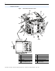
Drive Status Indicators and DPI Port Locations Figure 19 Drive Status Indicators and DPI Port Locations ➍ BR1 ➏ R Optional 1203-S03 Splitter Cable (located behind cross brace) T S ➎ ➊ ➌ (located behind ➋ cross brace) No. Name ➊ PWR (Power) ➋ STS (Status) Color Green State Steady Description Illuminates when power is applied to the drive.
Common I/O Programming Changes Your application needs may require changing parameters from their factory default settings. Speed Reference A Change Speed Reference A from Analog In 2 to Analog In 1 to connect an external potentiometer. 1. Set Parameter 090 [Speed Ref A Sel] to option “1” (Analog In 1). This sets the speed reference input to I/O terminals 14 and 15 for voltage and I/O terminals 16 and 17 for current. 2. Set Parameter 096 [TB Man Ref Sel] to option “9” (MOP Level).
Troubleshooting – Abbreviated Fault & Alarm Listing Decel Inhibit Type(1) Fault Auxiliary Input No. For a complete listing of Faults and Alarms, refer to the PowerFlex 700 Series B User Manual (publication 20B-UM002). Description ➀ Auxiliary input interlock is open. 24 ➂ The drive is not following a 2 commanded deceleration because it is attempting to limit bus voltage. Action Check remote wiring. 1. Verify input voltage is within drive specified limits. 2.
Type(1) Alarm Dig In ConflictA No. 47 17 ➁ Description Digital input functions are in conflict. Combinations marked with a “ ” will cause an alarm. Acc2/Dec2 Accel 2 Decel 2 Jog 1/2 Jog Fwd Jog Rev Fwd/Rev Acc2/Dec2 Accel 2 Decel 2 Jog 1/2 Jog Fwd Jog Rev Fwd/Rev Dig In ConflictB 18 ➁ A digital Start input has been configured without a Stop input or other functions are in conflict. Combinations that conflict are marked with a “ ” and will cause an alarm.
Common Symptoms and Corrective Actions Drive does not Start from Start or Run Inputs wired to the terminal block. Cause(s) Drive is Faulted Indication Flashing red status light Incorrect input wiring. Refer to the wiring examples starting on page 27. • 2 wire control requires Run, Run Forward, Run Reverse or Jog input. • 3 wire control requires Start and Stop inputs. • Jumper from terminal 25 to 26 is required. Incorrect digital input programming.
Drive does not respond to changes in speed command. Cause(s) Indication Corrective Action No value is coming from the source of LCD HIM Status Line 1. If the source is an analog input, check wiring and use a meter to the command. indicates “At Speed” check for presence of signal. and output is 0 Hz. Incorrect reference source has been programmed. Incorrect Reference source is being selected via remote device or digital inputs. None None 2. Check Parameter 002 [Commanded Speed] for correct source.
Drive will not reverse motor direction. Cause(s) Digital input is not selected for reversing control. Indication None Digital input is incorrectly wired. Direction mode parameter is incorrectly programmed. None None Motor wiring is improperly phased for reverse. A bipolar analog speed command input is incorrectly wired or signal is absent. None None Corrective Action Check Parameters 361…366 [Digital Inx Sel]. Choose correct input and program for reversing mode. Check input wiring.
Parameter List – Vector Control Option (v6.
Number 153 154 155, 156 157 158 159 160 161, 162 163 164 165 166 167 168 169 170 174 175 177 178 179 180 181 182 183 184 185 186 187 188 189 190 192 193 194 195 196 197 198 199 200 201 202 203 204 205 206 209, 210 211, 212 213 214 215 216 217 218 Parameter Name Regen Power Limit** Current Rate Limit** Stop Mode X DC Brk Lvl Sel DC Brake Level DC Brake Time Bus Reg Ki* Bus Reg Mode X DB Resistor Type Bus Reg Kp* Bus Reg Kd* Flux Braking Powerup Delay Start At PowerUp Flying Start En Flying StartGain Aut
Number 291 292 293 294 295 296 297 298 299 300…307 308 310…317 320 321 322, 325 323, 326 324, 327 340 341 342, 345 343, 346 344, 347 354, 355 361…366 377, 378 379 380, 384, 388 381, 385, 389 382, 386, 390 383, 387, 391 392 393 394 411 412 413 414 415 416 419 420 421 422 423 427, 431 428, 432 429, 433 430 434 435 436 437 438 440 441 Parameter Name Direction Owner Reference Owner Accel Owner Decel Owner Fault Clr Owner MOP Owner Local Owner DPI Ref Select DPI Fdbk Select Data In XX HighRes Ref 6.
Number 648 650 651 652 653 654…660 661 662 663 669 670 671 672 675 676 677 700 701 702 705 707 708 711 713 714 718 719 720, 730, 740, 750, 760, 770, 780, 790, 800, 810, 820, 830, 840, 850, 860, 870 Parameter Name Gearbox Limit Adj Volt Phase Adj Volt Select Adj Volt Ref Hi Adj Volt Ref Lo Adj Volt Preset1-7 Min Adj Voltage Adj Volt Command MOP Adj VoltRate Adj Volt TrimSel Adj Volt Trim Hi Adj Volt Trim Lo Adj Volt Trim % Adj Volt AccTime Adj Volt DecTime Adj Volt S Curve Pos/Spd Prof Sts Units Travele
Appendix Specifications Category Agency Certification Specification Listed to UL508C and CAN/CSA-C2.2 No. 14-M91. Marked for all applicable European Directives EMC Directive (2004/108/EC) EN 61800-3 Adjustable Speed electrical power drive systems Low Voltage Directive (2006/95/EC) EN 50178 Electronic Equipment for use in Power Installations The drive is also designed to meet the following specifications: NFPA 70 - US National Electrical Code NEMA ICS 3.
Category Environment (continued) Specification Relative Humidity: Shock: Vibration: Sinusoidal: Random: Electrical Input Voltage: Input Frequency Range: Line-to-Neutral Phase Imbalance Tolerance: Output Voltage: Output Frequency Range: Switching Frequency: Control Continuous Output Power: Continuous Output Current: Peak Output Current: 3 seconds Maximum: 1 minute: Efficiency at Maximum Power, Nominal Voltage: Power Loss at Full Load: Power Loss to Air: Method: Carrier Frequency: Output Voltage Ra
Category Control (continued) Liquid Coolant Encoder Dynamic Brake Resistor Specification Speed Control: Speed Regulation - without feedback (Vector Control Mode) 0.1% of base speed across 120:1 speed range 120:1 operating range 50 rad/sec bandwidth Speed Regulation - with feedback (Vector Control Mode) 0.
Derate Guidelines Altitude Above 1000 m (3280 ft), derate the output current by 1% for every 100 additional meters (328 additional feet). PowerFlex 700L Frame 1X drives should not be used above 2000 m (6562 ft) due to voltage spacing requirements. Ambient Frame 1X drives have a maximum ambient of 60 °C (140 °F). PowerFlex 700L drives cannot be derated to operate at higher temperatures. Carrier Frequency For Frame 1X drives, refer to the carrier frequency derating table below.
PowerFlex 700L Frame 1X Drive Installation Instructions – Publication 20L-IN013A-EN-P – June 2009
U.S. Allen-Bradley Drives Technical Support - Tel: (1) 262.512.8176, Fax: (1) 262.512.2222, Email: support@drives.ra.rockwell.com, Online: www.ab.com/support/abdrives *PN-47006* www.rockwellautomation.com PN-47006 Power, Control and Information Solutions Headquarters Americas: Rockwell Automation, 1201 South Second Street, Milwaukee, WI 53204 USA,Tel: (1) 414.382.2000, Fax: (1) 414.382.