
User Manual

4-4 Troubleshooting
PowerFlex 700L Active Converter Power Module User Manual
Publication PFLEX-UM002D-EN-P
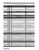
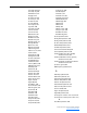
Table 4.B Fault Cross Reference – By Number
Clearing Alarms
Alarms are automatically cleared when the condition that caused the alarm
is no longer present.
Alarm Descriptions
All Active Converter alarms are configurable using parameter 260 - [Alarm
Config]. The status of the alarms can be viewed using parameter 211 -
[Alarm Status].
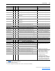
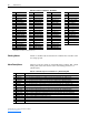
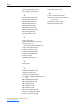
Table 4.C Alarm Descriptions for Parameter 211 - [Alarm Status] Bits
No.
(1)
Fault No.
(1)
Fault No.
(1)
Fault No.
(1)
Fault
1 HW Over Current 22 PS2 DSAT Phase T 43 Ac Sync Low Freq 66 PS1 Fan Loss
2 HW Over Voltage 23 PS2 Over Current 44 Ac Sync High Freq 67 PS1 Reactor Temp
3 HW Ground Fault 24 PS2 Over Voltage 45 Ac Sync Conflict 68 PS2 Fan Loss
4 HW Disabled 25 PS2 Asym DC Link 46 PWM Sync Lost 69 PS2 Reactor Temp
5 HW Latch Error 26 PS2 Power Supply 50 Ac Low Voltage 70 FiltCap Contactr
6 Precharge Open 27 PS2 HW Disable 51 Ac High Voltage 71 Port 1 Adapter
7 Precharge Closed 28 PS2 Latch Error 52 Ac Low Frequency 72 Port 2 Adapter
8 DPI Mstr ComLoss 30 PwrBd Incompat 53 Ac HighFrequency 73 Port 3 Adapter
9 Inverter Flt 31 PB Ver Corrupted 54 Ac High dFdt 74 Port 4 Adapter
10 PS1 DSAT Phase R 32 Default Corruptd 55 Ac I Imbalance 75 Port 5 Adapter
11 PS1 DSAT Phase S 33 Rating Corrupted 56 Ac V Imbalance 76 Port 6 Adapter
12 PS1 DSAT Phase T 34 New ControlBoard 57 DcLink Low Volt 81 Port 1 DPI Loss
13 PS1 Over Current 35 Elapsed CheckSum 58 Ride Thru Expire 82 Port 2 DPI Loss
14 PS1 Over Voltage 36 Param CheckSum 59 Ride Thru Expire 83 Port 3 DPI Loss
15 PS1 Asym DC Link 37 Param CheckSum B 60 IT Over Load 84 Port 4 DPI Loss
16 PS1 Power Supply 38 Param CheckSum W 61 Ambnt Over Temp 85 Port 5 DPI Loss
17 PS1 HW Disable 39 Param CheckSum L 62 Base Over Temp 86 Port 6 DPI Loss
18 PS1 Latch Error 40 Ac Line Lost 63 Junct Over Temp
20 PS2 DSAT Phase R 41 Ac Phase Lost 64 Ntc Range Low
21 PS2 DSAT Phase S 42 Ac Sync Low Vac 65 Ntc Range High
(1)
Fault numbers not listed are reserved for future use.
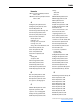
Bit Bit Definition Description
0 Ac Low Volt Bit 0 is set when the average AC Line Voltage is less than the limit in parameter 112 - [Low Vac Lmt].
1 Ac High Volt Bit 1 is set when the average AC Line Voltage exceeds the limit in parameter 114 - [High Vac Lmt].
2 Ac Low Freq Bit 2 is set when the AC Line Frequency is less than the limit in parameter 131 - [AC Low Freq Lmt].
3 Ac High Freq Bit 3 is set when the AC Line Frequency exceeds the limit in parameter 133 - [AC High Freq Lmt].
4 Ac High dFdt Bit 4 is set when the AC Line Frequency is changing faster than the limit in parameter 135 - [AC Maximum dF/dt].
5 I Imbalance Bit 5 is set when the phase current imbalance exceeds the limit in parameter 103 - [I Imbalance Lmt].
6 V Imbalance Bit 6 is set when the phase voltage imbalance is greater than the limit in parameter 116 - [V Imbalance Lmt].
7 IT Overload Bit 7 is set when the Overload counter is greater than 90%.
8 Ambient Temp Bit 8 is set when the ambient temperature exceeds the limit in parameter 120 - [Ambnt Temp Alrm].
9 Base Temp Bit 9 is set when the IGBT base temperature exceeds the limit in parameter 122 - [Base Temp Alrm].
10 Junction Temp Bit 10 is set when the IGBT junction temperature exceeds the limit in parameter 124 - [Junct Temp Alrm].
11 Coldplate Temp Bit 11 is set when the coldplate temperature is less than the limit in parameter 126 - [CldPlt Temp Alrm].
12 PWM SyncLoss Bit 12 is set when PWM carrier synchronization is lost.
13 Reserved
14 Reserved
15 Start Inhibit Bit 15 is set when one or more start inhibits are present.