
User Manual

Programming and Parameters 3-21
PowerFlex 700L Active Converter Power Module User Manual
Publication PFLEX-UM002D-EN-P
INPUTS & OUTPUTS
Digital Inputs
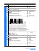
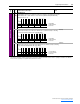
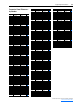
352 [Dig In Frc Data]
A set of bits to select the state of the input bits that are forced.
• Bit 0 (Aux Input) sets the state of the Aux Input signal when forcing is enabled. This feature requires a password to operate.
• Bit 1 (Sel Switch) sets the state of the DPI SLAVE/MASTER switch signal on the Active Converter control PCB assembly (Figure
1.3 on page 1-5) when forcing is enabled. This feature requires a password to operate.
Digital Outputs
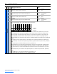
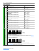
360 [Dig Out Status]
A set of bits displaying the status of the digital output.
• Bit 0 (Aux Output) is set when Aux Output is on.
• Bit 1 (Cls Bypass) is set when the precharge bypass contactor is closed.
Read Only
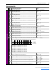
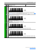
361 [Dig Out Frc Mask]
A set of bits to select which output bits are forced.
• Bit 0 (Aux Output) – Enables forcing of the Aux Output signal. This feature requires a password to operate.
• Bit 1 (Cls Bypass) – Enables forcing of the Cls Bypass signal. This feature requires a password to operate.
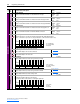
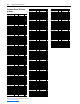
362 [Dig Out Frc Data]
A set of bits to select the state of the output bits that are forced.
• Bit 0 (Aux Output) sets the state of the Aux Output signal when forcing is enabled. This feature requires a password to operate.
• Bit 1 (Cls Bypass) sets the state of the Cls Bypass signal when forcing is enabled. This feature requires a password to operate.
File
Group
No. Parameter Name & Description Values
Bit
Definition
Sel Switch
Aux Input
Default xxxxxxxxxxxxxx00
Bit 1514131211109876543210
0 = Disabled
1 = Enabled
x = Reserved
Bit
Definition
Cls Bypass
Aux Output
Default xxxxxxxxxxxxxx00
Bit 1514131211109876543210
0 = Disabled
1 = Enabled
x = Reserved
Bit
Definition
Cls Bypass
Aux Output
Default xxxxxxxxxxxxxx00
Bit 1514131211109876543210
0 = Disabled
1 = Enabled
x = Reserved
Bit
Definition
Cls Bypass
Aux Output
Default xxxxxxxxxxxxxx00
Bit 1514131211109876543210
0 = Disabled
1 = Enabled
x = Reserved