
User Manual


3-16 Programming and Parameters
PowerFlex 700L Active Converter Power Module User Manual
Publication PFLEX-UM002D-EN-P
UTILITY
Fault Queue
247 [Fault 3 Code]
Displays the most third recent fault code detected.
Default:
Min/Max:
Units:
Read Only
0/65535
0
248 [Fault 3 Time]
Displays the time stamp for the most third recent fault detected.
Default:
Min/Max:
Units:
Read Only
0.0000/429496.7295
0.0001 Hrs
249 [Fault 4 Code]
Displays the most fourth recent fault code detected.
Default:
Min/Max:
Units:
Read Only
0/65535
0
250 [Fault 4 Time]
Displays the time stamp for the most fourth recent fault detected.
Default:
Min/Max:
Units:
Read Only
0.0000/429496.7295
0.0001 Hrs
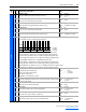
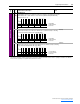
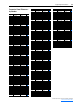
260 [Alarm Config]
A set of bits to enable/disable alarm conditions that will initiate a Converter alarm.
• Bit 0 (Ac Low Volt) sets an alarm when the average AC line voltage is less than the limit in parameter 112 - [Low Vac Lmt].
• Bit 1 (Ac High Volt) sets an alarm when the average AC line voltage exceeds the limit in parameter 114 - [High Vac Lmt].
• Bit 2 (Ac Low Freq) sets an alarm when the AC line frequency is less than the limit in parameter 131 - [AC Low Freq Lmt].
• Bit 3 (Ac High Freq) sets an alarm when the AC line frequency exceeds the limit in parameter 133 - [AC High Freq Lmt].
• Bit 4 (Ac High dFdt) sets an alarm when the AC line frequency is changing faster than the limit in parameter 135 - [AC Maximum
dF/dt].
• Bit 5 (I Imbalance) sets an alarm when the phase current imbalance exceeds the limit in parameter 103 - [I Imbalance Lmt].
• Bit 6 (V Imbalance) sets an alarm when the phase voltage imbalance is greater than the limit in parameter 116 - [V Imbalance
Lmt].
• Bit 7 (IT Overload) sets an alarm when the Overload counter is greater than 90%.
• Bit 8 (Ambient Temp) sets an alarm when the ambient temperature exceeds the limit in parameter 120 - [Ambnt Temp Alrm].
• Bit 9 (Base Temp) sets an alarm when the IGBT base temperature exceeds the limit in parameter 122 - [Base Temp Alrm].
• Bit 10 (Junction Temp) sets an alarm when the IGBT junction temperature exceeds the limit in parameter 124 - [Junct Temp
Alrm].
• Bit 11 (Coldplate Temp) sets an alarm when the coldplate temperature is less than the limit in parameter 126 - [CldPlt Temp
Alrm].
• Bit 12 (PWM SyncLoss) sets an alarm when PWM carrier synchronization is lost.
• Bit 15 (Start Inhibit) sets an alarm when one or more start inhibits are present.
File
Group
No. Parameter Name & Description Values
Bit
Definition
Start Inhibit
PWM SyncLoss
Coldplate Temp
Junction Temp
Base Temp
Ambient Temp
IT Overload
V Imbalance
I Imbalance
Ac High dFdt
Ac High Freq
Ac Low Freq
Ac High Volt
Ac Low Volt
Default 1xx1011111111111
Bit 1514131211109876543210
0 = Disabled
1 = Enabled
x = Reserved