
User Manual


Programming and Parameters 3-15
PowerFlex 700L Active Converter Power Module User Manual
Publication PFLEX-UM002D-EN-P
UTILITY
Diagnostic
230 [Fault Base Temp]
Displays the IGBT base temperature at the time of the fault.
Default:
Min/Max:
Units:
Read Only
-40.0/+150.0
0.1°C
234 [Testpoint 1 Sel]
Allows for access to other test points in the system.
Default:
Min/Max:
Units:
499
0/65535
1
235 [Testpoint 1 Data]
Displays the data selected in parameter 234 - [Testpoint 1 Sel].
Default:
Min/Max:
Units:
Read Only
-2147483647/+2147483647
1
236 [Testpoint 2 Sel]
Allows for access to other test points in the system.
Default:
Min/Max:
Units:
499
0/65535
1
237 [Testpoint 2 Data]
Displays the data selected in parameter 236 - [Testpoint 2 Sel].
Default:
Min/Max:
Units:
Read Only
-2147483647/+2147483647
1
Fault Queue
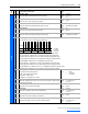
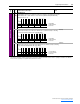
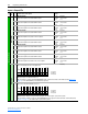
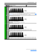
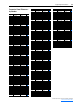
238 [Fault Config]
A set of bits that select which conditions may generate faults.
• Bit 0 (Ac Low Volt) – When this bit is set, low AC line voltage will generate a fault.
• Bit 1 (Ac High Volt) – When this bit is set, high AC line voltage will generate a fault.
• Bit 2 (Ac Low Freq) – When this bit is set, low AC line frequency will generate a fault.
• Bit 3 (Ac High Freq) – When this bit is set, high AC line frequency will generate a fault.
• Bit 4 (High dFdt) – When this bit is set, high dF/dt will generate a fault.
• Bit 5 (I Imbalance) – When this bit is set, high current imbalance will generate a fault.
• Bit 6 (V Imbalance) – When this bit is set, high voltage imbalance will generate a fault.
• Bit 7 (PWM SyncLost) – When this bit is set, loss of PWM synchronization will generate a fault.
• Bit 8 (Inverter Flt) – When this bit is set, a fault in the Inverter will fault the Converter.
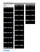
239 [Fault Clear]
Resets faults and clears the fault queue.
“Ready” = A new value may be entered.
“Clear Faults” = A fault is reset.
“Clr Fault Que” = The fault queue is cleared.
Default:
Options:
0
0
1
2
“Ready”
“Ready”
“Clear Faults”
“Clr Fault Que”
242 [Power Up Marker]
Displays the elapsed time at power up. This is used to know if a fault occurred since the
last time power was applied.
Default:
Min/Max:
Units:
Read Only
0.0000/429496.7295
0.0001 Hrs
243 [Fault 1 Code]
Displays the most recent fault code detected.
Default:
Min/Max:
Units:
Read Only
0/65535
0
244 [Fault 1 Time]
Displays the time stamp for the most recent fault detected.
Default:
Min/Max:
Units:
Read Only
0.0000/429496.7295
0.0001 Hrs
245 [Fault 2 Code]
Displays the most second recent fault code detected.
Default:
Min/Max:
Units:
Read Only
0/65535
0
246 [Fault 2 Time]
Displays the time stamp for the most second recent fault detected.
Default:
Min/Max:
Units:
Read Only
0.0000/429496.7295
0.0001 Hrs
File
Group
No. Parameter Name & Description Values
Bit
Definition
Inverter Flt
PWM SyncLost
V Imbalance
I Imbalance
High dFdt
Ac High Freq
Ac Low Freq
Ac High Volt
Ac Low Volt
Default xxxxxxx101101100
Bit 1514131211109876543210
0 = Disabled
1 = Enabled
x = Reserved