
User Manual

3-14 Programming and Parameters
PowerFlex 700L Active Converter Power Module User Manual
Publication PFLEX-UM002D-EN-P
UTILITY
Diagnostic
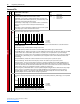
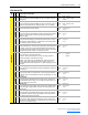
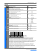
214 [Start Inhibit]
A set of bits displaying the interlocks that inhibit the Converter from starting.
• Bit 0 (Ac Low Volt) is set when the average AC line voltage is less than the limit in parameter 112 - [Low Vac Lmt].
• Bit 1 (Ac High Volt) is set when the average AC line voltage exceeds the limit in parameter 114 - [High Vac Lmt].
• Bit 2 (Ac Low Freq) is set when the AC line frequency is less than the limit in parameter 131 - [AC Low Freq Lmt].
• Bit 3 (Ac High Freq) is set when the AC line frequency exceeds the limit in parameter 133 - [AC High Freq Lmt].
• Bit 4 (Single Phase) is set when an input phase is missing.
• Bit 5 (Phased ACB) is set when an input phase voltage is phased ACB and parameter 051 - [Option Select] Bit 0 (AutoPhaseRot)
is not enabled.
• Bit 6 (DC Link Low) is set when DC Link voltage is too low to close the precharge bypass contactor.
• Bit 7 (High dv/dt) is set when DC Link dv/dt is too high to close the precharge bypass contactor.
• Bit 8 (Pchg Open) is set when the precharge bypass contactor is open and manual sequencing is selected.
• Bit 9 (PWM Not Sync) is set when Par 051 - [Option Select] Bit 3 (PWM SyncRecv) is turned on and synchronization is not completed.
• Bit 10 (Reqst Maintd) is set after a fault if the enable is not turned off. Restart requires a rising edge.
• Bit 11 (High DC Link) is set when Run On PwrUp is selected in parameter 50 - [Start Config] and the DC Link is greater than
1.44 times the value in parameter 114 - [High Vac Lmt]. On a 480 volt unit, parameter 114 - [High Vac Lmt] defaults to “528” so
inhibit Bit 11 (High DC Link) defaults to 760 volts.
• Bit 15 (Faulted) is set when the Converter is faulted.
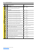
220 [Fault Frequency]
Displays the AC line frequency at the time of the fault.
Default:
Min/Max:
Units:
Read Only
0.0/100.0
0.1 Hz
221 [Fault Amps R]
Displays phase R peak current at the time of the fault.
Default:
Min/Max:
Units:
Read Only
-3276.7/+3276.7
0.1 Amps
222 [Fault Amps S]
Displays phase S peak current at the time of the fault.
Default:
Min/Max:
Units:
Read Only
-3276.7/+3276.7
0.1 Amps
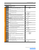
223 [Fault Amps T]
Displays phase T peak current at the time of the fault.
Default:
Min/Max:
Units:
Read Only
-3276.7/+3276.7
0.1 Amps
224 [Fault Amps Q]
Displays the real current at the time of the fault.
Default:
Min/Max:
Units:
Read Only
-3276.7/+3276.7
0.1 Amps
225 [Fault Amps D]
Displays the reactive current at the time of the fault.
Default:
Min/Max:
Units:
Read Only
-3276.7/+3276.7
0.1 Amps
226 [Fault Volts RS]
Displays the RMS line-to-line voltage between phase R and S at the time of the fault.
Default:
Min/Max:
Units:
Read Only
0.0/3276.7
0.1 Vac
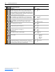
227 [Fault Volts ST]
Displays the RMS line-to-line voltage between phase S and T at the time of the fault.
Default:
Min/Max:
Units:
Read Only
0.0/3276.7
0.1 Vac
228 [Fault Volts TR]
Displays the RMS line-to-line voltage between phase T and R at the time of the fault.
Default:
Min/Max:
Units:
Read Only
0.0/3276.7
0.1 Vac
229 [Fault Volts Vdc]
Displays the DC Link voltage at the time of the fault.
Default:
Min/Max:
Units:
Read Only
0.0/3276.7
0.1 Vdc
File
Group
No. Parameter Name & Description Values
Bit
Definition
Faulted
High DC Link
Reqst Maintd
PWM Not Sync
Pchg Open
High dv/dt
DC Link Low
Phased ACB
Single Phase
Ac High Freq
Ac Low Freq
Ac High Volt
Ac Low Volt
Default 0xxx000000000000
Bit 1514131211109876543210
0 = Disabled
1 = Enabled
x = Reserved
Read Only