
User Manual

1-6 Installation/Wiring
PowerFlex 700L Active Converter Power Module User Manual
Publication PFLEX-UM002D-EN-P
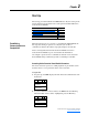
Table 1.B Active Converter Control PCB Assembly P1 Terminal Descriptions
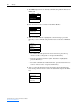
Table 1.C Voltage Feedback Resistor PCB Assembly P2 Terminal Descriptions
Specific pins on P1 and P2 terminals require control wiring connections to
the Input Filter Bay. For wiring information, please refer to the PowerFlex
700L Liquid-Cooled Adjustable Frequency AC Drive User Manual
(Publication No. 20L-UM001…).
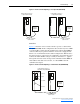
Using the Active Converter as a Coupled Unit vs. Standalone Unit
Frame 3B converter power structures may be ordered as a unit Coupled to
an inverter (DPI SLAVE), or as a Stand Alone unit (DPI MASTER). Frame
2 and Frame 3A power structures are always wired for the converter to be a
Coupled unit.
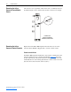
Coupled
Figure 1.4
shows the Active Converter wired to operate as a Coupled unit
(DPI SLAVE). In this configuration, the Converter is connected to a
PowerFlex 700L Inverter through DPI Port 6. When configured for "Run On
Start," the Converter is able to start and stop automatically as the Inverter is
started and stopped.
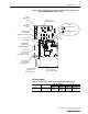
Pin Description
1Comm Out +
2Comm Out -
3 SOC Out +
4 SOC Out -
5 Comm In +
6 Comm In -
7 SOC In +
8 SOC In -
9Aux Out N.O.
10 Aux Out Common
11 Analog In Signal
12 Analog In Common
13 Gate Enable
14 24 Vdc
15 Aux Input
Pin Description
7L3
4L2
1L1