PowerFlex 700L Active Converter Power Module USER MANUAL Firmware Version 3.
Important User Information Solid state equipment has operational characteristics differing from those of electromechanical equipment. Safety Guidelines for the Application, Installation and Maintenance of Solid State Controls (Publication SGI-1.1 available from your local Rockwell Automation sales office or online at http://www.rockwellautomation.com/ literature) describes some important differences between solid state equipment and hard-wired electromechanical devices.
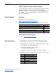
Summary of Changes The information below summarizes the changes resulting from the firmware v3.001 upgrade to this manual since its last release (June, 2006): Description of New or Updated Information To all pages, added a new footer containing: Page(s) Throughout Manual • Publication description (1st line). • Publication number hyperlink underlined in blue (2nd line) linking to the date of the publication on the back cover.
soc-ii Summary of Changes PowerFlex 700L Active Converter Power Module User Manual Publication PFLEX-UM002D-EN-P
Table of Contents Preface Overview Who Should Use this Manual? . . . . . . . . . . . . . . . . . . . . . . . . . . . . . . . . . . . . . . . . . . . . . What Is Not in this Manual . . . . . . . . . . . . . . . . . . . . . . . . . . . . . . . . . . . . . . . . . . . . . . . . LPM20 Liquid-Cooled AC Drive Installation . . . . . . . . . . . . . . . . . . . . . . . . . . . . . . . PowerFlex 700L Liquid-Cooled AC Drive Information . . . . . . . . . . . . . . . . . . . . . . .
ii Table of Contents Converter Faults. . . . . . . . . . . . . . . . . . . . . . . . . . . . . . . . . . . . . . . . . . . . . . . . . . . . . . . . Converter Faults as a Coupled Unit (DPI SLAVE) . . . . . . . . . . . . . . . . . . . . . . . . . . . Displaying the Fault Text. . . . . . . . . . . . . . . . . . . . . . . . . . . . . . . . . . . . . . . . . . . . . . . Resetting Converter Faults. . . . . . . . . . . . . . . . . . . . . . . . . . . . . . . . . . . . . . . . . . . . . .
Preface Overview The purpose of this manual is to provide you with the basic information needed to wire and operate the PowerFlex 700 Active Converter Power Module. For information on ... Who Should Use this Manual? What Is Not in this Manual Reference Materials Manual Conventions General Precautions See page ... P-1 P-1 P-2 P-2 P-3 Who Should Use this Manual? This manual is intended for qualified personnel. You must be able to wire and operate Adjustable Frequency AC Drive devices.
P-2 Overview PowerFlex 700S Phase II Control Information (optional) For PowerFlex Liquid-Cooled AC drives equipped with optional PowerFlex 700S Phase II Control, please refer to the PowerFlex 700S High Performance AC Drive — Phase II Control User Manual (Publication No. 20D-UM006…) which provides I/O wiring, start-up, programming, and other related information. Reference Materials Publications Publications can be obtained online at http://www.rockwellautomation.com/literature.
Overview General Precautions ! ! ! ! P-3 ATTENTION: This drive contains ESD (Electrostatic Discharge) sensitive parts and assemblies. Static control precautions are required when installing, testing, servicing or repairing this assembly. Component damage may result if ESD control procedures are not followed. If you are not familiar with static control procedures, refer to Allen-Bradley publication 8000-4.5.2, “Guarding Against Electrostatic Damage” or any other applicable ESD protection handbook.
P-4 Overview Notes: PowerFlex 700L Active Converter Power Module User Manual Publication PFLEX-UM002D-EN-P
Chapter 1 Installation/Wiring This chapter provides information on installing and wiring the PowerFlex 700 Active Converter Power Module. For information on… Removing the Active Converter Power Module Covers Removing the Active Converter Control Cassette Wiring the Active Converter Control Cassette I/O Terminals See page… 1-2 1-2 1-4 Most start-up difficulties are the result of incorrect wiring. Every precaution must be taken to assure that the wiring is done as instructed.
1-2 Installation/Wiring Removing the Active Converter Power Module Covers All converter covers, regardless of drive frame size, are similarly removed by unfastening the screws. A Frame 3B converter is shown as an example. PORT MOD NET A NET B (4 Screws) PowerFlex 700L Liquid-Cooled AC Drive Frame 3B Converter shown Removing the Active Converter Control Cassette Regenerative PowerFlex 700L Liquid-Cooled AC drives use an Active Converter Power Module equipped with a converter control cassette.
Installation/Wiring 1-3 Figure 1.1 Removing the Frame 2 and 3A Active Converter Control Cassette Detail Pin 1 40-Pin Ribbon Cable Synchronization Cable (For use with 700S Phase II Control only) Internal DPI Cable P1 Synchronization Cable (For use with 700 Vector Control only) SH LD SH LD P2 Communications Adapter Option Frame 3B Drives Figure 1.2 shows the location and removal of the Active Converter control cassette to access its terminal blocks for control wiring.
1-4 Installation/Wiring Wiring the Active Converter Control Cassette I/O Terminals All wiring should be installed in conformance with the applicable local, national, and international codes (e.g., NEC/CEC). Signal wiring, control wiring, and power wiring must be routed in separate conduits to prevent interference with drive operation. Use grommets, when hubs are not provided, to guard against wire chafing. ! ATTENTION: Do not route signal and control wiring with power wiring in the same conduit.
Installation/Wiring 1-5 Figure 1.3 Active Converter Control Cassette I/O Terminal, Cable Connection, and DPI SLAVE/MASTER Switch SW1 Locations J1 40-Pin Ribbon Cable Header Active Converter Control PCB Assembly SW1 J2 30-Pin Ribbon Cable Header ON J9 Synchronization Cable Header (700S Ph. II Control only) ON DPI SLAVE = OFF DPI MASTER = ON J4 Internal DPI Cable Header P1 I/O Terminals (see Table 1.
1-6 Installation/Wiring Table 1.B Active Converter Control PCB Assembly P1 Terminal Descriptions Pin 1 2 3 4 5 6 7 8 9 10 11 12 13 14 15 Description Comm Out + Comm Out SOC Out + SOC Out Comm In + Comm In SOC In + SOC In Aux Out N.O. Aux Out Common Analog In Signal Analog In Common Gate Enable 24 Vdc Aux Input Table 1.
Installation/Wiring 1-7 Figure 1.4 Active Converter Operating as a Coupled Unit (DPI SLAVE) Frame 3A with Converter as a Coupled Unit (DPI SLAVE) I n v e r t e r C o n v e r t e r Frame 3B with Converter as a Coupled Unit (DPI SLAVE) C o n v e r t e r HIM I n v e r t e r HIM Personal Computer Personal Computer 1203-USB or 1203-SSS Serial Converter 1203-USB or 1203-SSS Serial Converter Stand Alone Figure 1.5 shows the Active Converter wired to operate as a Stand Alone unit (DPI MASTER).
1-8 Installation/Wiring The Frame 3B Active Converter power module is ordered as a Stand Alone unit (DPI SLAVE) by specifying equipment type P in the catalog number (refer to the catalog number explanation in the PowerFlex 700L User Manual). The Stand Alone (DPI SLAVE) Active Converter is supported with Active Converter firmware revision 3.001 (or higher).
Chapter 2 Start Up The start-up procedure built into the HIM addresses only the start up of the inverter. This chapter describes how to start up the PowerFlex 700 Active Converter Power Module.
2-2 Start Up 3. The HIM displays that it is currently communicating with the Inverter on DPI Port 0. F-> Stopped 0.0 Auto RPM Device: Port 0 PowerFlex 700S 2 PowerFlex 700 AC 4. Press the Down arrow to scroll to “PowerFlex 700 AC.” F-> Stopped 0.0 Auto RPM Device: Port 6 PowerFlex 700S 2 PowerFlex 700 AC 5. With “PowerFlex 700 AC” highlighted as shown in Step 4, press the Enter key to start communicating with the Active Converter on DPI Port 6.
Start Up 2-3 7. The display then shows the groups of parameters in the selected file. Press the Up or Down Arrow to select the desired group and press the Enter key. Port 6 Device PowerFlex 700AC FGP: Group Current Voltage Power & Time 8. The display then shows the parameters in the selected group. Press the Up or Down Arrow to select the desired parameter and press the Enter key. Port 6 Device PowerFlex 700AC FGP: Parameter Rated Amps Input Current R Input Current S 9.
2-4 Start Up Using DriveExecutive When using DriveExecutive, the Active Converter parameters are displayed in a linear list. Uploading reads parameter values from all DPI peripherals but downloading parameters only write to the Inverter. To download parameter values to the Active Converter, you must first select the Converter.
Start Up 2-5 Exchanging Data DPI Type 3 communication is used to exchange control and status information between the Inverter and the Converter. This provides a mechanism to start and stop the Converter as the Inverter is started and stopped. It also transfers the minimum DC Link voltage required for the given motor voltage to the Converter, and any Converter fault codes back to the Inverter so all faults are maintained in the Inverter’s fault queue.
2-6 Start Up In addition to Type 3 communication, the 700S may optionally use DPI data links to control the sequencing of the Converter from a Logix processor as shown below. This requires the Converter to be configured for Manual Control in Converter parameter 50 - [Start Config]. The reference for the voltage loop may also be controlled by a Logix processor when Converter parameter 160 - [Voltage Loop Sel] is set to Manual Ref.
Start Up 2-7 CIP Messages Parameters in the Converter may be accessed by a Logix processor using a CIP message block. To read or write a parameter value you must respectively perform a Get Attribute Single or Set Attribute Single message to the DPI Parameter Object (Class 0x93). The Converter is in DPI Port 6, so the instance is 22528 plus the parameter number. The value of the parameter is accessed through Attribute 0x9 or 0xA.
2-8 Start Up Establishing Communication as a Stand Alone Unit When the Converter is set to operate as a Stand Alone unit (DPI MASTER), the first step after turning on power is to verify that you are able to communicate with the unit and that it properly displays selected data. Accessing Active Converter Power Module Parameters Using the HIM 1. On power up, the HIM displays the AC Line Frequency, the Active Current, and the DC Bus Voltage.
Start Up 2-9 Using DriveExplorer or DriveExecutive When using DriveExplorer or DriveExecutive, the Converter parameters are displayed under Port 0 and are organized into the normal menu of Files, Groups, and Parameters. The control bar can be opened to show a stop and start push button.
2-10 Start Up Using a 20-COMM-x Adapter When a 20-COMM-x network communication adapter is connected to the Converter, the Product Logic Command bits may be used to start and stop the Converter and to reset a fault. All other bits are reserved. The Product Logic Status bits may be used to determine the state of the Converter.
Start Up 2-11 synchronized to the AC line frequency and does not have a speed reference. The feedback value sent to the 20-COMM-x adapter is the measured AC line frequency, where a value of 32767 corresponds to 100.00 Hz. The Converter supports 16-bit data links so if all data links are configured in the 20-COMM-x then the Connection Parameters in the Logix Processor must be setup as shown here.
2-12 Start Up Converter Sequencing The condition when to start and stop the Converter must be configured in parameter 50 - [Start Config]. There are three ways to operate the Converter: Run On Start, Run On Power Up, and Manual Control. This also configures how the precharge bypass contactor operates.
Start Up 2-13 Run On PwrUp When Converter parameter 50 - [Start Config] is set to “1 = Run On PwrUp,” the precharge bypass contactor is automatically closed and the Converter is enabled shortly after power is turned on. The precharge will close as soon as the DC Link voltage is above the minimum required level and it has reached steady state. The precharge will remain closed when there is a fault in the Converter. When the fault is reset, the Converter will go back into run.
2-14 Start Up Alone unit (DPI MASTER) and is supplying power to a common bus, extra precaution must be taken. ! ATTENTION: When operating as a Stand Alone unit (DPI MASTER) or supplying power to a common bus, external logic must be used to make sure the precharge bypass contactor is closed and the Converter is running before running an Inverter. Likewise, all Inverters must stop if the precharge opens or the Converter stops.
Start Up 2-15 Frequency Limits The PWM Carrier Frequency is fixed at 4 kHz and cannot be changed. If operating on a generator, the normal range of acceptable AC line frequencies may need to be expanded. The limit of the rate of change may also need to be adjusted to allow the line synchronization to properly track the changes in frequency. See Converter parameters 131 - [AC Low Freq Lmt] through 135 - [AC Maximum dF/dt].
2-16 Start Up Voltage Loop Tuning The tuning of the voltage loop is a function of Converter parameter 162 [Capacitance], parameter 163 - [VML bandwidth], and parameter 164 [VML Damping]. In most cases, the default values for these three parameters should not need to be adjusted. When multiple Inverters are on a common bus, the combined DC link capacitance of the additional inverters must be entered into parameter 170 - [Bus Capacitance].
Start Up 2-17 run, a fault is generated. This fault can be disabled in parameter 238 - [Fault Config] bit 7 (PWM SyncLost). When operating as a Stand Alone unit (DPI MASTER) and PWM Carrier Synchronization is enabled, the Converter needs to know if it should synchronize to a 700VC or a 700S. This selection is done in parameter 51 [Option Select] Bit 6 (700VC Invtr). This bit must be set for a 700VC and cleared for a 700S.
2-18 Start Up 1. Rather than selecting Parameters, use the Up arrow to select “Diagnostics” and press the Enter key. Port 6 Device PowerFlex 700AC Main Menu: Diagnostics Parameter Device Select 2. The HIM then displays the Diagnostics menu. With “Events” selected, press the Enter key. Port 6 Device PowerFlex 700AC Diagnostics: Events Status Info Device Version 3. The HIM then displays the Diag: Events menu. With “View Event Queue” selected, press the Enter key.
Chapter 3 Programming and Parameters This chapter provides a complete listing and description of the Active Converter Power Module parameters. The parameters can be configured (viewed/edited) using an LCD HIM (Human Interface Module). As a convenient alternative, programming can also be performed using DriveExecutive™ or DriveExplorer™ software and a personal computer.
3-2 Programming and Parameters ➎ Default: 0 “Ready” Options: 0 1 “Ready” “Factory” Drive… 197 238 Ac Low Volt Rated ÷ 4/Rated*1.5 Amps 0.1 Amps Ac High Volt Rated Amps*1.5 Min/Max: Units: Ac Low Freq Default: Ac High Freq [Active I Lmt]] Sets the current limit used when the IGBT overload is less than 90% of the IT fault threshold. [Reset to Defaults] Resets all values in the Converter to the factory defaults. “Ready” = A new value may be entered. “Factory” = Parameters are reset.
Programming and Parameters File Group Parameters Monitor Current Rated Amps Input Current R Input Current S Voltage Rated Volts 010 Input Voltage RS 011 Input Voltage ST 012 Input Voltage TR 013 DcLink Voltage DcLink Ripple 014 015 Power & Time Rated Power AC Line kW Motoring kWh Regen kWh 023 Lifetime kWh 024 Elapsed Run Time 025 Life Run Time Life Power Time Life Pwr Cycles 026 027 028 Monit or Command Comm and Limit Config Limit 001 002 003 020 021 022 Input Current T Ground Curren
3-4 Programming and Parameters Group File Monitor File No. Parameter Name & Description Values 001 [Rated Amps] When operating as a Coupled unit, displays the same rated current as the inverter as the voltage class is changed. [Input Current R] [Input Current S] [Input Current T] Displays the measured RMS phase currents. [Ground Current] Displays the measured ground current. Default: Read Only Min/Max: Units: 0.0/3000.0 0.1 Amps Default: Read Only Min/Max: Units: 0.0/3000.0 0.
Group File Programming and Parameters No. Parameter Name & Description Values 024 [Life Time kWh] Displays the lifetime accumulated kWh. This parameter cannot be reset. Default: Read Only Min/Max: Units: Default: 0.0/429496729.5 0.1 kWh Read Only/Reset Min/Max: Units: 0.0000/429496.7295 0.0001 Hr Default: Read Only Min/Max: Units: 0.0000/429496.7295 0.0001 Hr Default: Read Only Min/Max: Units: 0.0000/429496.7295 0.
3-6 Programming and Parameters Group File Command File No. Parameter Name & Description Values 050 [Start Config] Selects the method by which the Active Converter is started. Default: 0 “Run On Start” Options: 0 1 2 “Run On Start” “Run On PwrUp” “Manual Cntrl” “Run On Start” = The Converter is started when the Inverter is put into run or jogged. The Enable Converter Bit 0 in parameter 70 - [Converter Control] is used to operate the precharge and enable the Converter.
Parameter Name & Description Values 053 [Turn Off Delay] This parameter is used when parameter 50 - [Start Config] is set to “0” (Run On Start) to select how long to keep the Converter enabled after the Inverter is stopped. [DcLink Reference] Sets the reference for the DC Link voltage when parameter 160 - [Voltage Loop Sel] is set to “1” (Manual Ref). [kVAR Reference] Sets the reference for the kVAR to produce. Positive values are a leading power factor and negative values are a lagging power factor.
Programming and Parameters Active I Lmt Ac Ride Thru Bus Reg Ena Cnvtr Active Prechg Closed Ac Line Sync Cnvtr Ready 0 0 0 0 0 0 0 0 0 0 0 0 Cnvtr Alarm kVAR Lmt [Converter Status] A set of bits sent from the Converter to the Inverter to indicate status. Regenerating 071 PWM SyncLock Values CML Comm Ok Parameter Name & Description Abort Decel No.
Programming and Parameters 3-9 Group File Limit Config File No. Parameter Name & Description Values 100 [Active I Lmt] Sets the current limit used when the IGBT overload is less than 90% of the IT fault threshold. [Active OL I Lmt] Sets the current limit used when the IGBT overload is more than 90% of the IT fault threshold, and parameter 150 - [Reduce Ilmt Sel] is set to “1” (enabled). [Reactive RateLmt] Sets how fast reactive current will change. Default: Rated * 1.
Programming and Parameters AC Line Voltage Group File 3-10 No. Parameter Name & Description 117 Default: [V Imbalance Time] Sets the time delay in detecting a voltage imbalance between phases. A fault or Min/Max: alarm may be generated if the calculated imbalance is greater than the limit set Units: by parameter 116 - [V Imbalance Limit] for this amount of time. 1.0 Sec [Ambnt Temp Alrm] Sets the alarm threshold for the maximum ambient temperature. Default: 60.0°C Min/Max: Units: Default: 30.
Programming and Parameters 3-11 Group File Dynamic Control File No. Parameter Name & Description Values 150 [Reduce Ilmt Sel] Enables the use of a reduced current limit when in overload. Default: 1 “Disabled” Options: 0 1 “Disabled” “Enabled” “Disabled” = The Converter current limit is always the value in parameter 100 [Active I Lmt].
Programming and Parameters Group File 3-12 No. Parameter Name & Description Values 162 [Capacitance] Sets the DC Link capacitance. When set to non-zero, this value is used to calculate the tuning coefficients for the voltage loop VML Ki and Kp. In the case of a Frame 2 or Frame 3A drive, this is the capacitance inside the drive. In the case of a Frame 3B drive, it is the capacitance in the Converter and one Inverter.
Programming and Parameters 3-13 No. Parameter Name & Description Values 196 [Param Access Lvl] Selects which parameters are accessible by the HIM. “Basic” = A minimal subset of parameters are accessible on the HIM. “Advanced” = All parameters are accessible on the HIM. [Reset to Defaults] Resets all values in the Converter to the factory defaults. “Ready” = A new value may be entered. “Factory” = Parameters are reset. [Reset Meters] Resets the elapsed kWh and run time parameters to zero.
Programming and Parameters Phased ACB Single Phase Ac High Freq Ac Low Freq Ac High Volt Ac Low Volt x DC Link Low x High dv/dt x Pchg Open [Start Inhibit] A set of bits displaying the interlocks that inhibit the Converter from starting. PWM Not Sync 214 Bit Definition Values Reqst Maintd Parameter Name & Description High DC Link No.
No. Parameter Name & Description Values 230 [Fault Base Temp] Displays the IGBT base temperature at the time of the fault. Default: Read Only Min/Max: Units: Default: -40.0/+150.0 0.
Programming and Parameters No. Parameter Name & Description Values 247 [Fault 3 Code] Displays the most third recent fault code detected. Default: Read Only Min/Max: Units: Default: 0/65535 0 Read Only Min/Max: Units: Default: 0.0000/429496.7295 0.0001 Hrs Read Only Min/Max: Units: Default: 0/65535 0 Read Only Min/Max: Units: 0.0000/429496.7295 0.
Programming and Parameters 3-17 [Data In A1] - Link A Word 1 [Data In A2] - Link A Word 2 Parameter number whose value will be written from a communications device data table. [Data In B1] - Link B Word 1 [Data In B2] - Link B Word 2 Parameter number whose value will be written from a communications device data table. [Data In C1] - Link C Word 1 [Data In C2] - Link C Word 2 Parameter number whose value will be written from a communications device data table.
Programming and Parameters No. Parameter Name & Description Values 325 [CS Msg Bad Cnt] Displays a counter that increments on a bad Client Server message.
DPI Port 2 DPI Port 1 [Write Mask Cfg] Enables/disables write access of parameters for DPI ports. Changes to this parameter only become effective when power is cycled, the drive is reset, or Bit 15 of parameter 348 - [Write Mask Act] transitions from “1” to “0.
3-20 Programming and Parameters No. Parameter Name & Description Values 330 [IGBT NTC Temp1] Displays the temperature measured in IGBT module 1. Default: Read Only Min/Max: Units: Default: -3276.7/+3276.7 0.1°C Read Only Min/Max: Units: Default: -3276.7/+3276.7 0.1°C Read Only Min/Max: Units: Default: -3276.7/+3276.7 0.1°C Read Only Min/Max: Units: Default: -3276.7/+3276.7 0.1°C Read Only Min/Max: Units: Default: -3276.7/+3276.7 0.1°C Read Only Min/Max: Units: Default: -3276.7/+3276.7 0.
352 [Dig In Frc Data] A set of bits to select the state of the input bits that are forced. Default x x x x x x x x x 0 0 Bit 15 14 13 12 11 10 9 8 7 6 5 4 3 2 1 0 Bit Definition x x x x x 3-21 Values Aux Input Parameter Name & Description Sel Switch Group No. Digital Inputs File Programming and Parameters 0 = Disabled 1 = Enabled x = Reserved • Bit 0 (Aux Input) sets the state of the Aux Input signal when forcing is enabled.
3-22 Programming and Parameters Parameter Cross Reference – by Name Parameter Name AC High Freq Lmt AC High Freq Time AC Line kW AC Low Freq Lmt AC Low Freq Time AC Maximum dF/dt Active Current Active I Cmd Active I Lmt Active OL I Lmt Alarm Config Alarm Status Ambient Temp Ambnt Temp Alrm Ambnt Temp Trip Base Temp Alrm Base Temp Trip Bus Capacitance CAN Bus Off Cnt Capacitance Change Line Freq CldPlt Temp Alrm CML Bandwidth CML Damping CML Ki CML Kp Coldplate Temp1 Coldplate Temp2 Connect Status Control
Programming and Parameters Parameter Cross Reference – by Number Number 001 002 003 004 005 006 007 008 009 010 011 012 013 014 015 016 020 021 022 023 024 025 026 027 028 030 031 032 040 041 042 043 044 050 051 052 053 060 061 062 063 064 070 071 072 073 100 101 102 103 104 105 110 111 112 113 114 115 116 117 120 121 122 123 124 125 126 130 131 132 133 134 Parameter Name Rated Amps Input Current R Input Current S Input Current T Ground Current Active Current Reactive Current I Imbalance IT Overload Rated
3-24 Programming and Parameters Notes: PowerFlex 700L Active Converter Power Module User Manual Publication PFLEX-UM002D-EN-P
Chapter 4 Troubleshooting This chapter provides information to guide you in troubleshooting the PowerFlex 700L Active Converter Power Module. Included is a listing and description of faults (with possible solutions, when applicable) and alarms. For information on … Faults and Alarms Manually Clearing Faults Fault Descriptions Clearing Alarms Alarm Descriptions Faults and Alarms See page… 4-1 4-1 4-1 4-4 4-4 A fault is a condition that stops the Converter. There are two fault types.
4-2 Troubleshooting Table 4.A Fault Types, Descriptions, and Actions Fault No.
Troubleshooting Fault PWM Sync Lost No. 46 Type (1) Description ➂ PWM Carrier synchronization was lost.
4-4 Troubleshooting Table 4.B Fault Cross Reference – By Number No. (1) 1 2 3 4 5 6 7 8 9 10 11 12 13 14 15 16 17 18 20 21 (1) Fault HW Over Current HW Over Voltage HW Ground Fault HW Disabled HW Latch Error Precharge Open Precharge Closed DPI Mstr ComLoss Inverter Flt PS1 DSAT Phase R PS1 DSAT Phase S PS1 DSAT Phase T PS1 Over Current PS1 Over Voltage PS1 Asym DC Link PS1 Power Supply PS1 HW Disable PS1 Latch Error PS2 DSAT Phase R PS2 DSAT Phase S No.
Index Numerics 700 Vector Control (standard) information reference, P-1 700S Phase II Control (optional) information reference, P-2 clearing alarms, 4-4 faults, 4-1 CML Bandwidth parameter, 3-11 CML Damping parameter, 3-11 CML Ki parameter, 3-11 A AC High Freq Lmt parameter, 3-10 AC High Freq Time parameter, 3-10 AC Line kW parameter, 3-4 AC Line Voltage Parameter Group, 3-9 AC Low Freq Lmt parameter, 3-10 AC Low Freq Time parameter, 3-10 Active Converter Power Module fault descriptions, 4-1 parameters, 3
Index-2 Data Out B1 parameter, 3-17 Fault Amps S parameter, 3-14 Data Out B2 parameter, 3-17 Fault Amps T parameter, 3-14 Data Out C1 parameter, 3-17 Fault Clear parameter, 3-15 Data Out C2 parameter, 3-17 Fault Clr Mask parameter, 3-18 Data Out D1 parameter, 3-17 Fault Clr Owner parameter, 3-18 Data Out D2 parameter, 3-17 Fault Config parameter, 3-15 Datalinks Parameter Group, 3-17 fault descriptions for active converter, 4-1 DcLink Command parameter, 3-11 Fault Frequency parameter, 3-14 D
Index-3 Voltage Loop, 3-11 Line Frequency parameter, 3-5 linear list of parameters, 3-23 H High Vac Lmt parameter, 3-9 High Vac Time parameter, 3-9 Logic Mask Act parameter, 3-19 Logic Mask parameter, 3-18 Low Vac Limit parameter, 3-9 Low Vac Time parameter, 3-9 I LPM20 liquid-cooled AC drive installation information reference, P-1 I Imbalance Lmt parameter, 3-9 I Imbalance parameter, 3-4 IGBT Base Temp parameter, 3-5 IGBT Junction Temp parameter, 3-5 IGBT NTC Temp1 parameter, 3-20 IGBT NTC Temp2 par
Index-4 Ambnt Temp Alrm, 3-10 Ambnt Temp Trip, 3-10 Base Temp Alrm, 3-10 Base Temp Trip, 3-10 Bus Capacitance, 3-12 CAN Bus Off Cnt, 3-18 Capacitance, 3-12 Change Line Freq, 3-5 CldPlt Temp Alrm, 3-10 CML Bandwidth, 3-11 CML Damping, 3-11 CML Ki, 3-11 CML Kp, 3-11 Coldplate Temp1, 3-20 Coldplate Temp2, 3-20 Connect Status, 3-17 Control SW Ver, 3-13 Converter Control, 3-7 Converter Fault, 3-8 Converter Min Vdc, 3-8 Converter Status, 3-8 CS Msg Bad Cnt, 3-18 CS Msg Rx Cnt, 3-17 CS Msg Tx Cnt, 3-17 CS Timeout
Index-5 Junct Temp Alrm, 3-10 Junct Temp Trip, 3-10 kVAR Reference, 3-7 Language, 3-13 Life Power Time, 3-5 Life Pwr Cycles, 3-5 Life Run Time, 3-5 Life Time kWh, 3-5 Line Frequency, 3-5 Logic Mask, 3-18 Logic Mask Act, 3-19 Low Vac Limit, 3-9 Low Vac Time, 3-9 Manual Control, 3-6 Min Line Freq, 3-5 Min Max Persist, 3-5 Modulation Freq, 3-7 Modulation Index, 3-7 Motoring kWh, 3-4 Option Select, 3-6 Output Powr Fctr, 3-4 Parallel Config, 3-12 Param Access Lvl, 3-13 Password, 3-13 PC Msg Rx Cnt, 3-18 PC Msg
Index-6 Reset to Defaults parameter, 3-13 Voltage Parameter Group, 3-4 Ride Through Sec parameter, 3-9 W S web site for reference literature, P-2 Setpoints Parameter Group, 3-7 wiring active converter control cassette I/O terminals, 1-4 Speed Mode parameter, 3-6 Write Mask Act parameter, 3-19 Start Inhibit parameter, 3-14 Write Mask Cfg parameter, 3-19 Security Parameter Group, 3-18 Start Mask parameter, 3-18 Start Owner parameter, 3-18 Start/Stop Parameter Group, 3-6 static discharge (ESD), P-
U.S. Allen-Bradley Drives Technical Support - Tel: (1) 262.512.8176, Fax: (1) 262.512.2222, Email: support@drives.ra.rockwell.com, Online: www.ab.com/support/abdrives www.rockwellautomation.com Power, Control and Information Solutions Headquarters Americas: Rockwell Automation, 1201 South Second Street, Milwaukee, WI 53204-2496 USA,Tel: (1) 414.382.2000, Fax: (1) 414.382.