
Owner manual


Overview P-3
PowerFlex 700L Liquid-to-Liquid Heat Exchanger User Manual
Publication 20L-UM002A-EN-P
Component Details
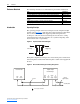
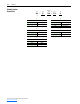
Figure P.3 shows a cooling loop diagram for a typical liquid-to-liquid heat
exchanger.
Figure P.3 Liquid-to-Liquid Heat Exchanger Plumbing Diagram
The main components of the cooling loop include:
General Precautions
Ambient Sensor
Heat Exchanger
Pump
Reservoir
Drive
IN
OUT
IN
OUT
OUT
IN
Drive Coolant Temp.
Control
Valve
Strainer
Supply
Process
Water
Flow Switch
Level Switch
TE
TE FS
LS
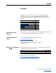
Part Description
Strainer Filters particles from the supply water.
Control Valve Controls the supply loop water flow.
Heat Exchanger Plate Transfers heat from the drive loop to the supply loop.
Ambient Sensor Senses the ambient temperature used for the dew point control.
Drive Coolant Temperature
Sensor
Senses the drive coolant temperature used for the dew point control.
Drive Coolant Flow Switch Measures the drive coolant flow rate.
Level Switch Senses the level of coolant in the reservoir.
Reservoir Stores drive coolant.
Pump and Motor Circulates drive coolant.
!
ATTENTION: An incorrectly applied or installed heat exchanger
can result in component damage or a reduction in product life.
Wiring or application errors, such as, undersizing the heat
exchanger, incorrect or inadequate AC supply, or excessive
ambient temperatures may result in malfunction of the system.
!
ATTENTION: Only qualified personnel familiar with adjustable
frequency AC drives and associated machinery should plan or
implement the installation, start-up, and subsequent maintenance
of the system. Failure to comply may result in personal injury and/
or equipment damage.