
Owner manual

1-10 Installation
PowerFlex 700L Liquid-to-Liquid Heat Exchanger User Manual
Publication 20L-UM002A-EN-P
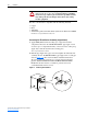
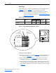
Power Wiring
Connect line power to the power terminal block’s L1, N, and PE terminals
(Figure 1.6
). Refer to Table 1.E for power terminal specifications.
Important: The heat exchanger is configured and shipped for 120 VAC
operation. However, its configuration can be changed to
operate on 230 VAC. For details, see Configuring for 230 VAC
Operation on page 1-10.
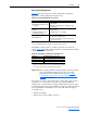
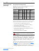
Table 1.E Power Terminal Specifications
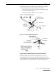
Figure 1.6 Power Terminal Block Electrical Connections
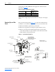
Configuring for 230 VAC Operation
1. Open the cover of the electrical box (Figure 1.1
) and set the J2 jumper on
the control board (Figure 1.7
) to the 230 VAC position (terminals 1-7).
2. On the power terminal block (Figure 1.6
), disconnect wire #3 from
terminal H2 and reconnect it to terminal H4 for 230 VAC operation.
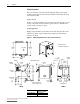
3. Remove the heat exchanger’s top panel first and then its left side panel to
access the pump motor conduit box. Remove the conduit box cover and
change the motor winding connections for 230 VAC operation as shown
in Figure 1.8
.
Name Description
Wire Size Range
(1)
Recommended
Tightening
Torque (+
10%)
Wire Strip
Length
Maximum Minimum
Input Power Terminals —
PE, N, and L1
Input AC line power 3.3 mm
2
(#12 AWG)
0.05 mm
2
(#30 AWG)
N/A
(Spring-Loaded)
10 mm
(0.4 in.)
(1)
Maximum/minimum sizes that the terminals will accept - these are not recommendations.
J2
J1
J5
J6
J7
J8
L1
N
H1
H2
H4
PE
PE
Wire #3
(115 VAC Line
Power Connection)
Wire #3
(230 VAC Line
Power Connection)