Liquid-to-Liquid Heat Exchanger User Manual
Important User Information Solid state equipment has operational characteristics differing from those of electromechanical equipment. Safety Guidelines for the Application, Installation and Maintenance of Solid State Controls (Publication SGI-1.1 available from your local Rockwell Automation sales office or online at http:// www.rockwellautomation.com/literature) describes some important differences between solid state equipment and hard-wired electromechanical devices.
Summary of Changes This is the first release of the PowerFlex 700L Liquid-to-Liquid Heat Exchanger User Manual.
soc-ii Summary of Changes PowerFlex 700L Liquid-to-Liquid Heat Exchanger User Manual Publication 20L-UM002A-EN-P
Table of Contents Preface Overview Who Should Use this Manual? . . . . . . . . . . . . . . . . . . . . . . . . . . . . . . . . . . . . . . . . . . . . . Technical Support and Service . . . . . . . . . . . . . . . . . . . . . . . . . . . . . . . . . . . . . . . . . . . . . What Is Not in this Manual . . . . . . . . . . . . . . . . . . . . . . . . . . . . . . . . . . . . . . . . . . . . . . . . Reference Materials . . . . . . . . . . . . . . . . . . . . . . . . . . . . . . . . . . . . . . . . . . . . . . . .
ii Table of Contents Chapter 2 Operation Drive Interaction . . . . . . . . . . . . . . . . . . . . . . . . . . . . . . . . . . . . . . . . . . . . . . . . . . . . . . . . Normal Operation . . . . . . . . . . . . . . . . . . . . . . . . . . . . . . . . . . . . . . . . . . . . . . . . . . . . . Loss of Flow Operation . . . . . . . . . . . . . . . . . . . . . . . . . . . . . . . . . . . . . . . . . . . . . . . . . PRIME SWITCH Operation . . . . . . . . . . . . . . . . . . . . . . . . . . . . . . . . . . . .
Preface Overview The purpose of this manual is to provide you with the installation and operating information for the PowerFlex 700L Liquid-to-Liquid Heat Exchanger used with PowerFlex 700L Liquid-Cooled drives and power modules.
P-2 Overview Reference Materials The following manuals are recommended for general drive information: Title Wiring and Grounding Guidelines for Pulse Width Modulated (PWM) AC Drives Preventive Maintenance of Industrial Control and Drive System Equipment PowerFlex 70/700 Reference Manual Safety Guidelines for the Application, Installation, and Maintenance of Solid State Control A Global Reference Guide for Reading Schematic Diagrams Guarding Against Electrostatic Damage Introduction Publication DRIVES-I
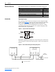
Overview P-3 Component Details Figure P.3 shows a cooling loop diagram for a typical liquid-to-liquid heat exchanger. Figure P.3 Liquid-to-Liquid Heat Exchanger Plumbing Diagram Ambient Sensor TE Control Valve Flow Switch TE FS Strainer IN OUT OUT Heat Exchanger Supply Process Water Drive Coolant Temp.
P-4 Overview Catalog Number Explanation 1-3 4 5-6 20L – LL a b 12 c A d e a d Hose Connection Type PowerFlex 700L Code P75 1P0 Size 0.75 inch NPT 1.
Chapter 1 Installation This chapter provides information on installing and wiring the PowerFlex 700L Liquid-to-Liquid Heat Exchanger.
1-2 Installation Lifting Instructions The heat exchanger can be lifted off the shipping skid by removing the packing material from the unit and unscrewing the mounting brackets lag screws from the skid. Using a Lift Truck Forks a can be inserted between the exchanger legs from the front or sides as long as the forks extend beyond the opposite surface. Note: Bottom sections of the exchanger are open.
Installation 1-3 Drive Coolant Requirements Table 1.A lists approved sources and recommended coolants with appropriate corrosion inhibitors for the drive loop: Table 1.A Recommended Drive Loop Coolants Source Interstate Chemical Coolant • NFP-50 (1); a 50/50 premix of propylene glycol and distilled water http://www.interstatechemical.com/ • NFE-50 (1); a 50/50 premix of ethylene glycol and contact.
1-4 Installation ! ATTENTION: Ethylene and propylene glycols must be inhibited and silicate free. Use of common silicate-containing, automotive-type ethylene glycol solutions is prohibited as they may damage the heat exchanger and/or drive and cooling module equipment. The drive coolant must be compatible with the following materials: • • • • Copper Brass Aluminum Arimid fiber gasket with nitrile binder (Garlock, Inc. Blue-Gard 3000®) Blue-Gard 3000 is a registered trademark of Garlock, Inc.
Installation 1-5 Supply Loop Liquid Quality, Maintenance, and Precautions ! ATTENTION: The single walled heat exchanger is not suitable for use in a potable water system. Do not connect the supply return to a potable water system. The supply loop liquid quality is not expected to be as clean as the drive loop liquid. Clean water will prolong the time needed between cleanings and/or replacement of the plate heat exchanger. A strainer with screen element is provided on the input of the supply loop.
1-6 Installation Connecting Hoses to the Heat Exchanger Drive Loop (from Heat Exchanger to Drive) Depending on the location of the heat exchanger relative to the drive, the following drive cooling loop hose kits are available: Table 1.
Installation 1-7 2. Using a backup wrench on the drive loop or drive fitting, tighten the swivel nut fitting by either of the following two methods: – Hex flats from wrench resistance method (recommended): one (1) hex flat from wrench resistance. – Torque method: 103 to 109 N-m (or 76 to 81 lb.-ft.). Figure 1.
1-8 Installation pressure drop of 5.00 to 6.00 PSI on the supply side, and flow must be provided per Table 1.D. Table 1.D Supply Loop Minimum Flow Rates Heat Exchanger Drive Size 20L-LL13K-P75A 20L-LL13K-P75A 20L-LL24K-1P0A Frame 2 Frame 3A Frame 3B Minimum Supply Loop Flow Rate 15.1 LPM (4 GPM) 22.7 LPM (6 GPM) 56.8 LPM (15 GPM) Connect the two supply loop hoses from the heat exchanger to the supply source. Removing Top and Side Panels The top panel and side panels (Figure 1.
Installation AC Supply Source Considerations 1-9 PowerFlex 700L Liquid-to-Liquid Heat Exchangers are suitable for use on a circuit capable of delivering up to a maximum of 5,000 rms symmetrical amperes or used on a circuit in conjunction with the appropriate current limiting devices. Fuses and Circuit Breakers Installation wiring requires the addition of circuit protection and disconnects as required by code.
1-10 Installation Power Wiring Connect line power to the power terminal block’s L1, N, and PE terminals (Figure 1.6). Refer to Table 1.E for power terminal specifications. Important: The heat exchanger is configured and shipped for 120 VAC operation. However, its configuration can be changed to operate on 230 VAC. For details, see Configuring for 230 VAC Operation on page 1-10. Table 1.
Installation 1-11 Figure 1.7 Control Board Component Locations 11 10 9 8 7 6 5 4 3 2 1 230 VAC Operation Plug Position J2 1 STATUS Indicator 115 VAC Operation Plug Position FU1 J3 S1 1 2 3 4 5 6 7 8 9 9 POWER Indicator J1 1 2 3 4 5 6 7 8 9 8 7 6 5 4 3 2 1 S2 S1 J4 S2 N O 8 7 6 5 4 3 2 1 N O 1 = ON = Down J5 1 J6 5 J7 1 10 J8 1 8 NOTE: Terminal blocks J3, J4, J5, J6, J7, and J8 do not require electrical connections by the user. Figure 1.
1-12 Installation Control Wiring Connect “run” and “interlock” control wiring from the PowerFlex 700L drive to the J1 connector on the control board. Refer to Table 1.F for control terminal specifications. Table 1.F Control Board Terminal Specifications Wire Size Range (1) Recommended Tightening Maximum Minimum Torque (+10%) Coolant Controller Control Control wiring for run, fault and 3.3 mm2 0.2 mm2 0.55 N-m Wiring Terminal Block — J1 alarm (optional), and interlock (#12 AWG) (#24 AWG) (5 lb.-in.
Installation 1-13 Control Interlock Wiring The interlock contact output on the heat exchanger control board can be interlocked (Figure 1.10 or Figure 1.11) with the PowerFlex 700L drive to prevent the drive from running when the heat exchanger is in a faulted state. Figure 1.
1-14 Installation Setting the DIP Switches Two 8-position DIP switches (S1 and S2 in Figure 1.7) set the various operating functions for the coolant controller. The DIP switch settings may be changed at any time while power is applied. A “1” indicates the switch is in the ON (down) position. S1 DIP Switch Settings See the descriptions below and Table 1.
Installation 1-15 S2 DIP Switch Settings See the descriptions below and Table 1.H for S2 switch settings: • SW1 (Start Input) — Sets the type of start for the heat exchanger. An edge-triggered (default) start requires a low-to-high transition of the run signal to start the heat exchanger. Since the drive will send the run signal, the edge-triggered start should be used.
1-16 Installation CE Conformity Compliance with the Low Voltage (LV) Directive and Electromagnetic Compatibility Directive (EMC) has been demonstrated using harmonized European Norm (EN) standards published in the Official Journal of the European Communities. PowerFlex 700L Liquid-to-Liquid Heat Exchangers comply with the EN standards listed below when installed according to this PowerFlex 700L Liquid-to-Liquid Heat Exchanger User Manual. CE Declarations of Conformity are available online at: http://www.
Chapter 2 Operation This chapter provides information on operating the PowerFlex 700L Liquid-to-Liquid Heat Exchanger.
2-2 Operation PRIME SWITCH Operation The PRIME SWITCH (Figure 2.1) will start the pump independently from the run state of the heat exchanger. Operating Status Indications The STATUS indicator (Figure 2.1) shows the operating status of the heat exchanger. Table 2.A lists its possible indications. Table 2.A Heat Exchanger Operating Status Indications (STATUS Indicator) LED Indication Red Steady Amber Description Internal fault that is non-resettable (state = internal fault).
Operation 2-3 Adding Coolant to the Drive 1. Make sure all hose connections are completed as described in Drive Loop (from Heat Exchanger to Drive) on page 1-6. Loop for Start-Up 2. With the top and side covers removed from the heat exchanger, make sure all wiring to the heat exchanger is completed as described in Power Wiring on page 1-10 and Control Wiring on page 1-12, respectively. 3. Make sure both pipe plugs are tightened on the drains in front of the heat exchanger. 4.
2-4 Operation 9. Entrapped air must be removed for the heat exchanger to function properly. Remove the fill tube cap and depress the PRIME SWITCH for 2-3 minutes. 10. Replace and tighten the fill tube cap on the tank. 11. Reinstall the top and side covers on the heat exchanger. The recommended tightening torque is 0.9 N-m (8 in-lbs.). Draining Supply Side Cooling Loop for Periodic Maintenance ! ATTENTION: Risk of equipment damage exists.
Operation 2-5 7. After flow stops, push the PRIME SWITCH for 8 seconds to open the motorized valve (see Figure 2.2). ! ATTENTION: Risk of equipment damage exists. Pressing the PRIME SWITCH longer than 20 seconds may damage the pump if the drive loop is already drained. 8. Clean off any old thread sealer from inside the pipe located on the heat exchanger and the removed plug. 9. Apply PTFE (Teflon®) thread sealing tape or pipe thread sealant compound to threads on the plug. 10.
2-6 Operation 8. Apply PTFE (Teflon®) thread sealing tape or pipe thread sealant compound to threads on the plug. 9. Use a 9/16 inch or adjustable wrench to reinstall the plug to the “DRIVE DRAIN” pipe on the front of the heat exchanger. (There is no need to use a backup wrench on the pipe nipple.) 10. Reconnect the hoses on the rear of the heat exchanger marked “TO DRIVE INLET” and “FROM DRIVE OUTLET” using the tools and method outlined in Connecting Hoses to the Heat Exchanger on page 1-6. 11.
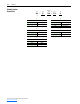
Appendix A Supplemental Heat Exchanger Information Specifications Category Specification Used with PowerFlex 700L: Agency c UL Certification ® Environment Electrical Input Drive Loop Supply Loop US Ambient Temperature: Storage Temperature: Atmosphere: Relative Humidity: Shock: Vibration: Input VAC: Pump HP: Frequency: Maximum Input Amps: Short Circuit Rating: Heat Dissipation: Flow @ Pressure: Temperature Range: Minimum Flow @ Pressure: Maximum Pressure: Temperature Range: Heat Exchanger Catalo
A-2 Supplemental Heat Exchanger Information Notes: PowerFlex 700L Liquid-to-Liquid Heat Exchanger User Manual Publication 20L-UM002A-EN-P
Appendix B Heat Exchanger Schematic Please refer to pages B-2 and B-3 for the schematic of the PowerFlex 700L Liquid-to-Liquid Heat Exchanger.
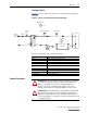
B-2 Heat Exchanger Schematic To GND Term Block External Power Connections 12 AWG Green/Yellow FRAME GND Term Block PE PANEL GND AC POWER Field Installation GND NEUTRAL HOT GND Term Block N 109CON L1 Term Block L1 Transformer Input Wiring X1 107CON 2 16 AWG Red 240V Orange 24 VAC 1 16 AWG Red Brown Term Block H4 Yellow Red H3 White X2 111MV Valve Motor + - Term Block H1 16 AWG White 16 AWG Green 5+ 6- 12 VDC 120 VAC 16A (Maximum) Flow Switch 113FLS COM (Red) NC (Blue) NO (Yellow)
Heat Exchanger Schematic B-3 NOTE: Default factory wiring is for operation at 115VAC, 60Hz. Pump Wiring 115V Motor: Emerson SFE06821S 60Hz 1.0 HP 3450 RPM 115/208-230 Volts 12.2 / 6.4-6.1 FLA GND Brown Orange Yellow White 50Hz 1.0 2850 220-230 7.3-7.7 Blue Pump: Goulds Pump, ITT Series MCS Size 1x 1 1/4-6 Cat. No. 1MS1E4D4 Impeller Dia. 4-3/4 Pump Wiring 230V GND White Orange Brown Yellow See Figure 1.7 on page 1-11 for 115 or 230 VAC operation J2 jumper settings. Blue 0.
B-4 Heat Exchanger Schematic Notes: PowerFlex 700L Liquid-to-Liquid Heat Exchanger User Manual Publication 20L-UM002A-EN-P
U.S. Allen-Bradley Drives Technical Support - Tel: (1) 262.512.8176, Fax: (1) 262.512.2222, Email: support@drives.ra.rockwell.com, Online: www.ab.com/support/abdrives www.rockwellautomation.com Power, Control and Information Solutions Headquarters Americas: Rockwell Automation, 1201 South Second Street, Milwaukee, WI 53204-2496 USA,Tel: (1) 414.382.2000, Fax: (1) 414.382.