
Manual

Rockwell Automation Publication 20GY-IN001A-EN-P - June 2011
PowerFlex® 755 with OEM Liquid Cooling Frame 6 and 7 AC Drives 11
Power Wiring
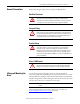
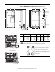
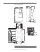
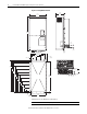
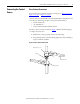
Refer to the information in the PowerFlex 750-Series AC Drive Installation
Instructions (publication 750-IN001) to wire power to the PowerFlex 755 with
OEM Liquid Cooling Frame 6 and 7 AC drives. However, see Tab l e 3
for the
recommended AC line input protection devices to use instead of the protection
devices listed for the standard, air-cooled PowerFlex 755 Frame 6 and 7 drives in
the PowerFlex 750-Series AC Drives Technical Data (publication 750-TD001).
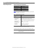
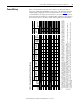
Table 3 - Recommended AC Input Protection Devices
Applied
Rating
(1)
(1) “Applied Rating” refers to the motor that will be connected to the drive. For example, a “C367” drive can be used in Normal Duty mode on a 200 kW motor, or in Heavy Duty mode
on a 160 kW motor. A “C260” drive can be used in Heavy Duty mode on a 110 kW motor with the same ratings as a “C205.” The drive can be programmed for either mode. Wiring
and fuses can be sized based on the programmed mode. For any given drive catalog number, Normal Duty mode provides higher continuous current but smaller overload current
with respect to Heavy Duty mode. See parameter 306 [Duty Rating].
Frame
Continuous
Output
Amps
Drive Sized For Normal
Duty
Drive Sized For Heavy
Duty
Input
Quantities AC Input Protection Devices
Input
Quantities
DC Input
Protection
Catalog
Number
Output
Overload
Amps
Catalog
Number
Output
Overload
Amps
Continuous
AC Input
Dual Element
Time Delay
Fuse
Non-Time
Delay Fuse
Circuit
Breaker
Maximum
Size
(4)
(4) Circuit Breaker - inverse time breaker. For US NEC, minimum size is 125% of motor FLA. Ratings shown are maximum.
Motor
Circuit
Protector
(5)
(5) Recommended Motor circuit protector - Instantaneous trip circuit breaker. The trip setting should be set to the input current of the drive and should be sized for the continuous
current of the system.
Continuous DC
Input
Non-Time Delay
Fusex = GY 1 min 3 sec 1 min 3 sec kVA Amps Min
(2)
(2) Minimum protection device size is the lowest rated device that supplies maximum protection without nuisance tripping.
Max
(3)
(3) Maximum protection device size is the highest rated device that supplies drive protection. For US NEC, minimum size is 125% of motor FLA. Ratings shown are maximum.
Min
(2)
Max
(3)
kW Amps
400 Volt AC Input 540 Volt DC Input
110 kW 6 205 20x…C260 307.5 390.0 139.1 200.8 275 450 275 600 600 400
132 kW 6 260 20x…C260 286.0 390.0 176.5 254.7 325 575 325 750 700 400
160 kW 7 302 20x…C367 453.0 550.5 205.0 295.9 400 675 400 900 900 600
200 kW 7 367 20x…C367 403.7 550.5 20x…C477 550.5 684.0 249.1 359.5 475 800 475 1000 1100 600
270 kW 7 477 20x…C477 524.7 715.5 388.5 467.3 600 1000 600 1200 1200 600
480 Volt AC Input 650 Volt DC Input
150 Hp 6 186 20x…D248 279.0 372.0 145.2 174.6 250 400 250 600 550 250
200 Hp 6 248 20x…D248 272.8 372.0 193.6 232.8 325 550 325 700 700 400
250 Hp 7 302 20x…D361 453.0 543.6 235.7 283.5 400 675 400 900 900 600
300 Hp 7 361 20x…D361 397.1 541.5 20x…D477 541.5 649.8 281.8 338.9 475 800 475 1000 1000 600
400 Hp 7 477 20x…D477 524.7 715.5 372.3 447.8 600 1000 600 1200 1200 600
Notes: