
Owner manual

Specifications A-15
PowerFlex SCR Bus Supply User Manual
Publication 20S-UM001G-EN-P
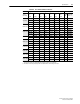
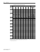
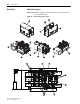
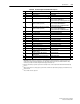
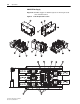
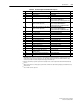
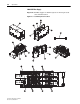
Table A.E 400A Unit Spare Part Numbers/Descriptions
Item Availability
(1)
Description Rockwell Catalog No. Qty.
3 — 400A SCR Set SK-20S-MCC162-18IO1 3
4 Yes Fan Assembly
(2)
SK-D9-FAN2 1
6 — 400A and 600A MOV Assembly SK-20S-VBKSDK041 1
7 Yes 40A Fuse (Precharge fuses F6…F8)
(3)
SK-20S-F070B040S or
Westcode Type F070B040S or
Ferraz Shawmut Type 6.921CPgRC14.51 40
3
8 Yes 400A, 700V Fuse (AC fuses F1…F3)
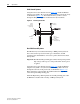
Torque to 13 N•m (115 lb•in).
SK-20S-069UR0S0400B or
Westcode Type 069UR0S0400B or
Ferraz Shawmut Type 6.9URD30TTF0400
3
9 Yes 450A, 700V Fuse (DC fuses F4 and F5)
Torque to 13 N•m (115 lb•in).
SK-20S-069UR0S0450B or
Westcode Type 069UR0S0450B or
Ferraz Shawmut Type 6.9URD30TTF0450
2
12 Yes Fuse Monitoring Switch SK-20S-MS3V1-5 5
13 — 85 °C Thermostat SK-20S-SWT85KSDKRW 1
16 — 400A SCR Wire Harness SK-20S-ZY041-400 1
18 Yes 400 and 600A Snubber Circuit Board SK-20S-PR-GR3 1
20 — 400A Cover SK-20S-RW9582300-B 1
21 — 400A Enclosure SK-20S-RW-U-SCR400 1
24 — 10 µF, 1200V Capacitor SK-20S-E62K85103D1W 2
25 — 5.6K Ohm, 90W Resistor SK-20S-RW35FST5K6K 2
27 — 4.7 Ohm, 45W Resistor SK-20S-RW33FST4R7K 1
30 — 400A Bus Bar Set SK-20S-BBKSDK041 1
31 — Terminal Block Assembly SK-20S-TBKSDKRW 1
32 — 40 mm tall x 40 mm O.D. Insulator
with M10 Thread
SK-20S-IN551520 3
33 — 30 mm tall x 26 mm O.D. Insulator
with M8 Thread
SK-20S-IN551450 2
35 Yes 480V SCR Precharge Circuit Board
(4)
SK-D9-SCRPRE1-D 1
38 Yes Precharge Relay SK-20S-CA2KN31F7 1
(1)
Important: SCR Bus Supplies are designed to be field maintained only. Normal maintenance components (fan, fuses, fuse
monitor switch, printed circuit boards (precharge, gate, and snubber), and precharge relay are available. Additional catalog
numbers are provided for troubleshooting and technical support information only.
(2)
Extensive disassembly is required to replace the fan assembly. Please consider using Rockwell Automation Remanufacturing
Services.
(3)
When replacing these fuses, always properly position them so that their fuse trip indicators (plungers) point toward the fuse trip
detection board.
(4)
This is an ESD sensitive component.