
Owner manual
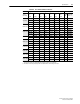
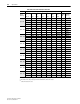

A-12 Specifications
PowerFlex SCR Bus Supply User Manual
Publication 20S-UM001G-EN-P
Solid Ground Systems
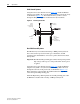
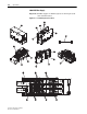
Using the hole location dimensions from Figure A.6, install the HF filter
using the four (4) M4 x 20 screws through the four holes in the plastic body
of the HF filter (Figure A.7
). Then install the three (3) M4 x 8 screws
through the PE grounding plate. Do NOT use the nylon standoffs.
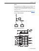
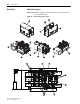
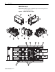
Figure A.7 Mounting the HF Filter
Non-Solid Ground Systems
The HF filter may be installed with floating or HRG ground systems for
line-to-line transient protection. In this type of installation, the PE
grounding plate should NOT be connected to ground, but remain isolated
from ground.
Important:The HF filter PE grounding plate will be floating with potential
high voltage with respect to earth ground when AC line power
is applied.
Using the hole location dimensions from Figure A.6
, install the HF filter
using the four (4) M4 x 19 nylon standoffs and four (4) M4 x 20 screws
through the four holes in the plastic body of the HF filter (Figure A.7
).
Finger tighten the nylon standoffs. Do NOT install the three (3) M4 x 8
screws through the PE grounding plate.
Install the High Voltage Warning label onto the PE grounding plate when
the HF filter is installed with a floating or HRG ground system.
M4 x 8
3 Places
(for solid ground
system only)
M4 x 20
4 Places
PE
Grounding
Plate
M4 x 19
Nylon Standoffs
4 Places
(for floating or
HGR system only)