
Owner manual

Specifications A-3
PowerFlex SCR Bus Supply User Manual
Publication 20S-UM001G-EN-P
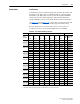
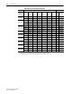
Bus Supply Dimensions
The overall dimensions and mounting holes of the PowerFlex SCR Bus
Supply are shown in Figure A.1
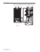
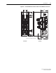
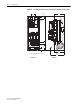
. Connection Bus Bar dimensions are shown
in Figure A.2
, Figure A.3, and Figure A.4.
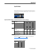
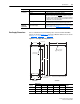
Figure A.1 Bus Supply Mounting Dimensions
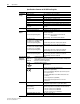
Environment
(continued)
Shock: 15G peak for 11 ms duration (± 1.0 ms)
Vibration: 0.152 mm (0.006 in.) displacement, 1G peak
Atmosphere: Important: The bus supply must
not be installed in an area
where the ambient atmosphere contains volatile or corrosive
gas, vapors or dust. If the bus supply is not going to be installed
for a period of time, it must be stored in an area where it will not
be exposed to a corrosive atmosphere.
Surrounding Environment: The fan has a L10 rated life of 74,000 hours in a clean
environment. Execessive dust and heat will degrade fan life.
Permitted
Maximum
Capacitance
Maximum Capacitance for Connection
to the DC Bus Supply
This is the total DC Bus capacitance sum of the permitted
drives to connect. See Minimum Capacitance
on page 1-6 and
Jumper Settings
on page 1-12.
Category Specification
SCR Bus
Supply
Dimensions
WeightABCDE
400A 535 (21.1) 404 (15.9) 580 (22.8) 276 (10.9) 138.5 (5.5) 30 kg (66 lb.)
600A 740 (29.1) 490 (19.3) 785 (30.9) 276 (10.9) 104.5 (4.1) 43 kg (95 lb.)
1000A 740 (29.1) 490 (19.3) 785 (30.9) 276 (10.9) 104.5 (4.1) 67 kg (147 lb.)
200 (7.87)
30 (1.2)
Ø 9.5 (0.37)
Not provided
on 400A Units
Ø 35 (1.4) Holes
for Lifting Hooks
Dimensions are in millimeters and (inches).
9.5
(0.37)
29
(1.14)
339.5
(13.4)
B
E
C
D
A
17 x 5 (0.67 x 0.2)
Slots for Precharge
Board LEDs
Side ViewFront View