
Owner manual

Start Up/Troubleshooting 2-5
PowerFlex SCR Bus Supply User Manual
Publication 20S-UM001G-EN-P
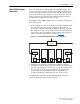
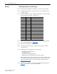
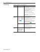
Table 2.A Precharge Board LED Indicators
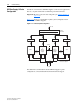
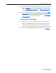
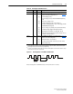
Figure 2.2 Flashing Pattern for ALARM and FAULT LEDs
Example: Flashing pattern for ALARM LED showing a Low Phase alarm (where n = 3 flashes)
Name Color State Description
POWER OK Green Steady Illuminates when precharge board power supply is operational.
ALARM Yellow Flashing The number [n] of flashes (see flashing pattern in Figure 2.2
)
indicates one of the following alarms
(1)
:
(1)
The ALARM indicator LED will continue the flashing pattern as long as the alarm condition exists. An alarm
might trigger internal actions which may stop SCR gate firing.
[1]
[2]
[3]
[4]
[5]
[6]
[7]
Low Line Voltage (< 90%)
Low Line Voltage (< 65%) for SCR and RGU/AFE paralleling
mode
Very Low Line Voltage (< 50%)
Low Phase (One phase < 80% of line voltage), or
Low Phase Voltage (One phase < 56% of line voltage) for SCR
and RGU/AFE paralleling mode
Freq. out of range or asymmetry (Line synchronization failed)
Low DC Bus Voltage (triggers ride-through operation)
Input Frequency momentarily out of range (40…65 Hz)
DC Bus Short Circuit testing active (repetitive for appr. 120 s) or
no inverter connected to the bus
FAULT Red Flashing The number [n] of flashes (see flashing pattern in Figure 2.2
)
indicates one of the following faults
(2)
:
(2)
If a fault occurs, the FAULT indicator LED will continue the flashing pattern, even if the fault condition no longer
exists. Power must be cycled to clear the fault.
[2]
[4]
[5]
DC Bus Short (Udc < 2% after 20ms)
Line Synchronization failed or Low Line (Uac < 50% Unom)
Jumper setting wrong
Pause
0.3
sec.
0.3
sec.
0.9 sec.