
Owner manual
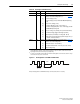

Start Up/Troubleshooting 2-3
PowerFlex SCR Bus Supply User Manual
Publication 20S-UM001G-EN-P
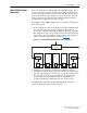
❏ 9. Verify that the SPARE 1 and SPARE 2 jumpers on the Precharge Board
shown in Figure 2.1
are set to appropriate positions for the application.
(Refer to Jumper Settings
on page 1-12 and Figure 1.9 on page 1-13 for
more information).
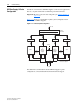
❏ 10. Verify that the jumper between control terminals 12 and GND (Figure
1.7 on page 1-11) is present on grounded supply lines (default) or is
removed on non-solid grounded supply lines. (Refer to Disconnecting
MOVs on page 1-14 for more information).
Applying AC Power to the Bus Supply
❏ 1. Apply AC power and control voltage (115V AC) to the Bus Supply.
The green POWER OK LED on the Precharge Board should be on if
power is applied to terminals L1 (R), L2 (S), L3 (T) and the enable
contactor for the precharge board (not used on Slave units) is energized.
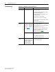
❏ 2. If the green POWER OK LED is off at this point, refer to Table 2.B
.