
Owner manual

2-2 Start Up/Troubleshooting
PowerFlex SCR Bus Supply User Manual
Publication 20S-UM001G-EN-P
Start-Up
Before Applying Power to the Bus Supply
❏ 1. Verify that the minimum of one Inverter is connected to the DC bus.
❏ 2. Confirm that all inputs are connected to the correct terminals and are
properly torqued.
❏ 3. Using an ohmmeter or other continuity testing device, verify that shorts
do not exist between Source 1 and Source 2:
❏ 4. Verify that AC line power at the disconnect device is within the rated
value of the Bus Supply. See Appendix
A.
❏ 5. Verify that control power voltage is correct.
❏ 6. Verify that the enable contactor coil K1 (not used on Slave units) is
correctly wired.
❏ 7. Verify that these four outputs are correctly wired:
– Bus Supply Overtemperature
– Rectifier Fuse Trip
– Snubber/DC feedback Fuse Trip
– Enable Contactor Feedback (not used on Slave units)
These normally closed contact outputs are used to set alarms and to stop
the drive(s). Verify that they have been wired correctly according to the
user’s specification. Refer to the control wiring example shown in
Figure 1.8 on page 1-12
.
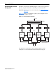
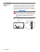
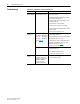
❏ 8. Verify that the “Line Type” jumper on the Precharge Board shown in
Figure 2.1
is set to the “3-ph” position (default).
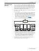
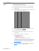
Source 1 Source 2 Checkmark Below if No Short Exists
L1 L2
L1 L3
L2 L3
L1 PE
L2 PE
L3 PE
L1 DC+ Bus
L2 DC+ Bus
L3 DC+ Bus
L1 DC- Bus
L2 DC- Bus
L3 DC- Bus
DC+ Bus DC- Bus
DC+ Bus PE
DC Bus PE