
Owner manual

Installation/Wiring 1-13
PowerFlex SCR Bus Supply User Manual
Publication 20S-UM001G-EN-P
active front end that is used only as a regenerative brake unit. The
PowerFlex SCR Bus Supply will then deliver the required motoring
power and the RGU/AFE will provide the possibility to feed the
regenerative energy back to the AC power line. The auto-voltage
limitation (allowing the SCRs to phase back) associated with high AC
line will be disabled. The left (RGU/AFE) jumper position provides the
best protection for parellel SCR and RGU/AFE operation.
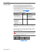
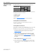
• SPARE 2 Jumper: For board firmware version 1.21 (or earlier), this
jumper is non-functional. For firmware version 1.22 (or later), this
jumper is used for slow ramp-up, which slows the DC bus voltage charge
up time (from 0.2 to 1.3 seconds). Slow ramp-up should be used when
the connected DC bus capacitance is greater
than the values shown in the
following table.
To operate the SCR Bus Supply with a slow ramp-up, set the SPARE 2
jumper to the left (SLOW) position.
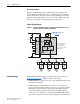
For standard applications where only the PowerFlex SCR Bus Supply
provides the required common DC power, make sure the SPARE 1 and
SPARE 2 jumpers are in their default settings (right side—towards the
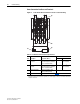
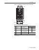
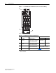
board edge) shown in Figure 1.9
.
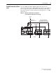
Figure 1.9 Location of LED Indicators and Jumpers on the Precharge Board
SCR Bus Supply
Max. Bus Capacitance
(1)
with Normal Ramp
(1)
It is recommended to derate the capacitance value by 20% in master/slave configurations.
Max. Bus Capacitance
(1)
with Slow Ramp
400A 40,000 µF 200,000 µF
600A 60,000 µF 300,000 µF
1000A @ 480V 100,000 µF 500,000 µF
1000A @ 690V 50,000 µF 250,000 µF
SPARE
2
(Ramp-Up)
Precharge Board
Firmware Version Label
(SCR and
RGU/AFE
Paralleling)
Slow Norm
Yes No
1-ph 3-ph
SPARE
1
LINE
TYPE
POWER
OK
ALARM LEDs
Jumpers shown in
default positions
FAULT
TIP: To identify the firmware version, remove the SCR Bus Supply cover
and check the firmware version label on the Precharge Board (Figure 1.9
).