
Owner manual

Installation/Wiring 1-11
PowerFlex SCR Bus Supply User Manual
Publication 20S-UM001G-EN-P
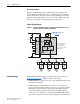
Control Wiring
Important points to remember about control wiring:
• Use Copper wire only. Wire gauge requirements and recommendations
are based on 75 °C (168 °F). Do not reduce wire gauge when using
higher temperature wire.
• Wire with an insulation rating of 600V or greater is recommended.
• Control wires outside the cabinet should be separated from power wires
by at least 0.3 meters (1 foot).
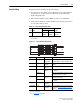
Table 1.F Control Terminal Specifications
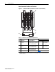
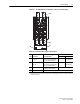
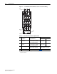
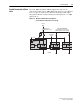
Figure 1.7 Control Terminal Arrangement
Item Name
Wire Size Range
(1)
(1)
Maximum/minimum sizes that the terminals will accept - these are not
recommendations.
TorqueMaximum Minimum
➍
Control Terminals 2.5 mm
2
(14 AWG)
0.25 mm
2
(22 AWG)
0.8 N•m
(7 lb•in)
Terminal Bus Supply Description Notes
115 and 0 All units 115V AC
Supply Input
For cooling blower (and power supply on the
Gate Driver Board - on Master and Slave Units)
1 and 2
(1)
(1)
Not used on Slave Units.
Contactor Coil
115V AC
Contactor must be energized to enable the
controller
4 and 5
(1)
NC Contact
Output
(2)
(2)
Refer to Appendix A for contact rating.
Opens if the Enable Contactor is energized
6 and 7 400A and 600A
units
NC Contact
Output
(2)
Opens if any of the snubber circuit fuses
(F6…F8) trip
1000A units Opens if any of the snubber circuit fuses or DC
bus feedback fuses (F7…F11) trip
8 and 9 400A and 600A
units
NC Contact
Output
(2)
Opens if any of the line input or DC bus branch
circuit fuses (F1…F5) trip
1000A units Opens if any of the line input branch circuit fuses
(F1…F6) trip
10 and 11 All units NC Contact
Output
(2)
Opens at power stack heat sink overtemperature
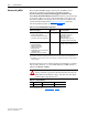
12 and GND All units Jumper MOVs
to Ground
Disconnects MOVs from ground by removing this
jumper. (See Disconnecting MOVs
on page 1-14
for details.)
12
11
10
9
8
7
6
5
4
2
1
0
115
GND
12
11
10
9
8
7
6
5
4
2
1
0
115
GND