
Owner manual

1-8 Installation/Wiring
PowerFlex SCR Bus Supply User Manual
Publication 20S-UM001G-EN-P
Power Connection Bus Bars and Terminals
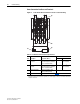
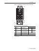
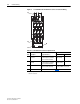
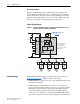
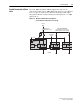
Figure 1.4 400A Unit Bus Bar and Terminal Locations for Customer Wiring
Table 1.C 400A Unit Power Connection Specifications
Item Description Copper Bus Bars
(1)
(1)
Input/output power bus bar connections require the use of either lug type connectors to terminate field-installed
conductors or bus bars.
Recommended Minimum Size
Bus Bar Wire
➊
AC Line Input
L1, L2, L3
40 x 5 mm (1.57 x 0.2 in.) with
single 14 mm (0.55 in.) diameter
hole for customer terminal
40 x 5 mm 120 mm
2
(or 2 x 50 mm
2
)
➋
DC Bus
DC+, DC-
40 x 5 mm (1.57 x 0.2 in.) with
single 14 mm (0.55 in.) diameter
hole for customer terminal
40 x 5 mm 150 mm
2
(or 2 x 70 mm
2
)
➌
Protective Earth PE M8 x 25 mm (0.98 in.) stud;
torque to 6 N•m (54 lb•in)
Size per NEC or local code
➍
Control Terminal Block See Tabl e 1.F
DC+
DC-
L1
L2
L3
➋
➊
➌
➍