
Owner manual

P-6 Overview
PowerFlex SCR Bus Supply User Manual
Publication 20S-UM001G-EN-P
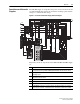
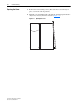
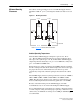
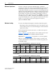
Figure P.2 1000A SCR Bus Supply Single Unit Schematic Diagram
The primary electrical components for the 1000A SCR Bus Supply Single
Unit are:
NOTE: There is no DC output fuse protection in the 1000A SCR unit.
>°C
F12
1
X1
3
X3
X2
G4
C4
G1
C1
C3
G3
C6
G6
G2
C2
G5
C5
K1
L1 L2 L3
A2
A1
F6
F1
F4
F5
F2
F3
F7 - 11
L1 L4L5L3L2
K1
22
4321 3313
443414
X1
GND
12
115
0
1
4
2
5
6
8
7
9
10
11
3
2
V3
4
5
3
2
V5
4
5
3
2
V1
4
5
3
2
V4
45
3
2
V6
45
3
2
V2
45
L1
L2
L3
PE
1
5
4
3
2
1
8
7
5
4
2
6
M
N
GND
L1
➋
➌
➊
➑
➏
➍
➎
Precharge
Board
+ DC
- DC
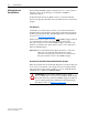
Item Description
➊
Six-Pulse, Full-Wave, 3-Phase SCR Bridge Rectifier Unit connected to the line input and DC
Bus output terminals through semi-conductor protection fuses with trip indicator switches.
➋
Bus Supply Overtemperature Sensor located on the heat sink for thermal protection of the
SCR bridge rectifier.
➌
RC snubber circuit routed to the three input phases through semi-conductor protection
fuses with trip indicator switches.
➍
MOV snubber circuit routed to the three input phases.
➎
Precharge Board
➏
Enable Contactor (K1) for the precharge board.
➑
Cooling Blower connected to a customer-supplied 115V AC Power Supply. The customer’s
controls must, at a minimum, command the blower to run whenever contactor K1 is enabled.